
User manual


Detaileddescriptionsoftheeld-buscoupler| Modbus TCP eld-bus coupler UR20-FBC-MOD-TCP
52 1432790000/03/02.2014Manual u-remote
5.4 ModbusTCPeld-buscouplerUR20-FBC-MOD-TCP
The UR20-FBC-MOD-TCP eld-bus coupler is a Modbus TCP
participant developed according to IEC 61158. The coupler
is the head module for the u-remote system bus, to which up
to 64 active u-remote modules can be connected. The Mod-
bus TCP coupler has two Ethernet ports, and the integrated
switch supports a line network structure.
The coupler can be activated with a system-independent
web server application via the USB service interface or the
Ethernet. In addition, all information, such as diagnostics,
status values and parameters, can be exported and all con-
nected modules can be simulated or forced.
The station's main power supply is integrated in the coupler.
Power is supplied via two 4-pole connectors, separated into
the input and output current paths.
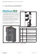
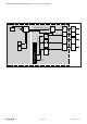
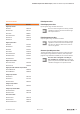
Field-buscouplerUR20-FBC-MOD-TCP(OrderNo.1334930000)
Status indicators
PWR
SF
BF
MT
MOD-TCP
P2
P1
1
2
3
4
1
2
3
4
LINK1
ACT1
ACT2
LINK2
3
4
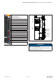
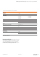
LEDstatusindicatorsUR20-FBC-MOD-TCP
PWR
Power LED Green: Supply voltage
SF
Collective error Red: Conguration error, or error in the coupler,
or error in a module, or there is a new diagnostic
report
Redashing: Station in Force mode
BF
Bus failure Red: No connection to the eld-bus
Redashing: Conguration error, no connection
to the control unit, or error in the parameter set
MT
Maintenance Yellow: Error on the system bus or eld-bus
L/A X1
Connection/active Green / Yellow*: Connection established between
port 1 of the coupler and another eld device
Greenashing/Yellowashing*: Data being
exchanged on port 1
L/A X2
Connection/active Green: Connection established between port 2 of
the coupler and another eld device
Greenashing: Data being exchanged on port 2
*Green:Transferrate100MBit/s
Yellow:Transferrate10MBit/s