
User manual


Detailed descriptions of I/O modules | Digital input module with time stamp UR20-2DI-P-TS
87Manual u-remote1432790000/03/02.2014
Time stamp function
With time stamp function (ETS = edge time stamp) enabled,
at every corresponding edge the time value of the timer is
stored in the process image as an ETS entry together with
the status of the inputs and a running number.
The module does not use any bytes in the output range. It
uses 60Bytes in the input range for 15ETS entries each
with 4bytes.
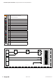
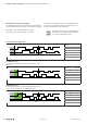
Structure of an ETS entry
Input map After the edge transition, the status of the inputs
is stored here. The input byte has the following
bit assignments:
Bit 0: DI0
Bit 1: DI1
Bit 2 … 7: reserved (0)
Running
Nummer
The RN (running number) is a consecutive
number from 0 to 127. The RN describes the
chronological sequence of the edges
Time stamp The 16-bit timer (0 ... 65535μs) in the u-remote
module is started as soon as the power supply
ist switched on and after (2
16
-1)μs restarts at 0.
Structure of the ETS entries in the input range in chronologi-
cal order.
t
0 µs 0 µs 65535 µs65535 µs
Adr. PII RN ETS_US
+16 PII-4 RN-4 ETS-US-4
+12 PII-3 RN-3 ETS-US-3
+8 PII-2 RN-2 ETS-US-2
+4 PII-1 RN-1 ETS-US1
+0 PII-0 RN-0 ETS-US-0