
User manual


System overview | General description of I/O modules
12 1432790000/03/02.2014Manual u-remote
3.3 General description of I/O modules
1
2
3
4
5
6
7
8
6
12
11
9
10
15
14
13
13
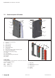
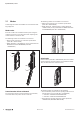
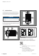
I/Omodule(ExampleUR20-4-DI-P)
1 Catch lever for securing the DIN rail
2 System bus
3 System current path
4 Input current path
5 Output current path
6 Seats for module markers
7 Type designation
8 Optional: swivel marker for labelling modules and channels
9 Connector frame unlocking device
10 Module status LED (collective message)
11 Connector
12 Channel status LEDs
13 Latching hook for latching onto module sides
14 DIN rail foot
15 Type plate
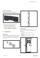
Colourcoding
The removal levers for the electronic unit and the connectors
are colour-coded as follows:
Black standard
Grey power supply
Red 230V
Yellow SIL products
1
2
3
4
5
6
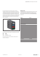
I/O module components
1 Basic module
2 Electronic unit
3 Removal lever for electronic unit
4 Connector frame
5 Connector
6 Plug-in unit