
User manual

Detailed descriptions of I/O modules | Digital counter module UR20-1CNT-100-1DO
131Manual u-remote1432790000/03/02.2014
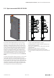
CountermoduleUR20-1CNT-100-1DO(OrderNo.1315570000)
The counter module UR20-1CNT-1DO-100 can read sig-
nals (e.g. from an incremental encoder) with a max. input
frequency of 100kHz. The 32-bit counter can count up or
down within a predetermined range of values. The counter
can be controlled using software or externally through the
latch, gate and reset inputs. A digital output can be param-
etrized to be activated immediatly upon dropping below,
meeting or exceeding the set comparison value. In order to
make it possible for the PLC to always recognise the signal
in its sequential operations in case ofvery fast events, an
overrun time can be provided with the parameter Pulse du-
ration.
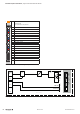
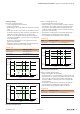
In counter mode, CH0A on plug-in connector 1 can be used
as the input and CH0B as a direction-detection input. In
incremental mode, an incremental encoder with track A and
B can be connected and at the same time supplied with op-
erating voltage. The control inputs are then connected to the
other plug-in connectors. A status LED is assigned to each
channel. The module electronics supply the connected sen-
sors with power from the input current path (U
IN
).
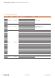
1
2
3
4
2
1
3
4
1
2
3
4
2
4
3
1
1CNT100
1
2
3
4
2
1
3
4
1
2
3
4
2
4
3
1
1CNT100
CH0 A
Track A
Track B
GND
24 V DC
CH0 B
DO
GND
24 V DC
RESET
LATCH
GND
24 V DC
GATE
Incremental
CH0 A
Cycle
GND
24 V DC
CH0 B
DO
GND
24 V DC
RESET
LATCH
GND
24 V DC
GATE
Direction 0/1 (24 V)
ConnectiondiagramUR20-1CNT-100-1DO
– 1 32-bit counter (AB) invertible, 24VDC
– Counting frequency 100kHz max (AB 1/2/4-times sam-
pling or pulse and direction)
– Latch value, comparision value, setting value, input filter
(parametrizable)
– HW gate reset, digital output for comparison
– Alarm and diagnostic function with μs time stamp
– μs time stamp for counting value (e.g. for speed measure-
ments)
6.15 DigitalcountermoduleUR20-1CNT-100-1DO