
User manual


Detailed descriptions of I/O modules | Digital counter module UR20-2CNT-100
158 1432790000/03/02.2014Manual u-remote
Comparison function
The comparison values for the two counter channels are
preset using the rst two double words of the process data
outputs. If the comparison bit was released via control word
the bit “Comparison condition met” of the status word is acti-
vated as soon as the comparison condition is met.
The following behaviour can be set for the comparison bit
through parametrizing:
– No comparison: the comparison bit is not affected
– Counter value ≥ comparison value: comparison bit is set
– Counter value ≤ comparison value: comparison bit is set
– Counter value = comparison value: comparison bit is set
No comparison
The comparison bit is not affected.
The comparison bit is set when the counter value ≥ compari-
son value
The comparison bit remains set until the counter value is
larger than or equal to the comparison value.
The comparison bit is set when the counter value ≤ compari-
son value
The comparison bit remains set until the counter value is less
than or equal to the comparison value.
The comparison bit is set when the counter value ≤ compari-
son value
The comparison bit is set as soon as the counter value
equals the comparison value. The bit remains set until the
comparison condition is no longer met.
If a primary counting direction has been set, the output
switches only upon reaching the comparison value from the
primary counting direction.
The bit “comparison condition met” is activat-
ed together with the bit “Comparison bit set”
of the status word. In contrast to the “Compari-
son bit set” bit it remains active until it is reset
with the bit “Reset status bits” of the control
word.
Hysteresis
It is possible to prevent frequent switching of the output and/
or triggering of the alarm, e.g. if the value of a sensor signal
fluctuates around the comparison value, by setting the hys-
teresis. A range between 0 and 255 can be preset for the
hysteresis. Hysteresis is deactivated with the values 0 and 1.
Hysteresis affects a zero-crossing, overow/underow and
comparison value.
Active hysteresis remains active after the change. The new
hysteresis range is active during the next hysteresis event.
The behaviour of the status bits for hysteresis 0 and hyster-
esis 3 are shown in the following diagrams for the corre-
sponding conditions.
Status bits are not reset automatically. The reset always
needs to be done via reset bit of the control word. Therefore
hysteresis does not affect the reset behaviour of the status
bits but their reset enabling and retrigger behaviour.
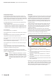
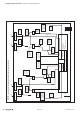
Operating principle when counter value ≥ comparison value
Counting value
Hysteresis = 0
Hysteresis = 3
1
2 3
4 7
5
6
Comparison
value
1 Counter value ≥ comparison value ➝ status bit is set and hysteresis acti-
vated
2 Leaving the hysteresis range ➝ status bit is reset enabled
3 Counter value ≥ comparison value ➝ status bit is set and hysteresis acti-
vated
4 Upon leaving the hysteresis range, the status bit remains set because the
counter value ≥ comparison value
5 Counter value < comparison value and hysteresis active ➝ status bit is
reset enabled
6 Counter value ≥ comparison value ➝ status bit is not set because hyster-
esis is activated
7 Upon leaving the hysteresis range, the status bit is set because the counter
value ≥ comparison value
Hysteresis is active upon reaching the comparison condition.
The comparison result remains unchanged during active hys-
teresis until the counter value leaves the set hysteresis range.
After leaving the hysteresis range, hysteresis is reactivated
only upon reaching the comparison condition again.