
User manual


Earthingandshielding| Shielding of cables
250 1432790000/03/02.2014Manual u-remote
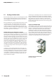
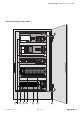
1 Earthing strips
Earthing strips must be used for connecting inactive metal
parts if it is not possible to connect two large pieces of met-
al. Use short earthing strips with large surfaces.
2 Clamping bracket for signal cables
If shielded signal cables are used, the shield must be at-
tached to the clamping bracket (KLBÜ series) on the busbar
over a large surface. The braided shield must cover and make
good contact with a large part of the clamping bracket.
3 Mounting plate
The support beam for holding control components must be
connected to a large part of the cabinet housing.
4 Busbar
The busbar must be connected via the rail holding xture.
The cable shields are xed to the busbar.
5 Protective earth conductor rail
The protective earth conductor rail must likewise be attached
to a large part of the mounting plate, and it must be con-
nected to the protective earth conductor system via an exter-
nal cable with a cross-section of at least 10 mm
2
, in order to
discharge interference current.
6 Protective earth terminal strip
The protective earth terminal strip must be connected to the
protective earth conductor rail in a neutral-point congura-
tion.
7 Cable to protective conductor system (earthing
point)
The cable must be connected to a large part of the protective
conductor system.
Seealso:
EMC Directive 2004/108/EC
8.4 Shieldingofcables
To prevent the coupling of interference voltages and the de-
coupling of interference elds in cables, only shielded cables
made from well-conducting material (copper or aluminium)
with braided shielding and a coverage of at least 80 %
should be used in the design of a cable shield.
Only when a cable shield is connected to the local refer-
ence potential on both sides is it possible to achieve optimal
shielding against electric and magnetic elds. Exceptions
are possible, for example, with high-impedance, symmetrical
or analogue signal cables. If a shield is attached on only one
side, this merely achieves an isolation against electric elds.
ATTENTION
Material damage!
Requirements for effective shielding design:
– The shield connection to the shield bus should be low
impedance
– The shield must be connected directly at its entrance
into the system
– Keep cable ends as short as possible
– Do not use cable shields for equipotential bonding
When connecting a data cable using a sub-D connector, the
connection must be made through the connector's shield
collar and never through pin 1.
The data cable's shield must be attached to the shield bus
with the insulation stripped away. The shield is to be con-
nected and attached with clamping brackets or similar metal
xing devices. The shield bus must be connected to the refer-
ence potential surface through a low impedance (e.g.fasten-
ing point with a separation of 10 to 20cm). The brackets
must surround and make contact with a large part of the
shield.
Isolation of the cable shield should be avoided. Instead, it
should be routed into the system (for example, the switch
cabinet) up to the interface connection.
ATTENTION
Shielding of eld bus cables
When shielding eld-bus cables, the installation guidelines
for the respective eld buses must be observed. (See the
websites of the eld bus organisations.)