
User manual


LED indicators and troubleshooting | I/O modules
287Manual u-remote1432790000/03/02.2014
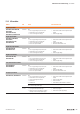
13.2 I/O modules
Module LED Status Recommended action
Digital input modules
UR20-4DI-P, UR20-8DI-P-3W,
UR20-16DI-P,
UR20-16DI-P-PLC-INT,
UR20-2DI-P-TS, UR20-2DI-P-TS
Status LED Red:
– Error in supply voltage at input current path
– Communication error on the system bus
– There is a new diagnostic message
– Check that the module has been snapped into place
properly
– Check the supply voltage
Digital output modules
UR20-4DO-P, UR20-8DO-P,
UR20-16DO-P,
UR20-16DO-P-PLC-INT,
UR20-4DO-PN-2A
Status LED Red:
– Error in supply voltage at output current path
– Communication error on the system bus
– There is a new diagnostic message
– At least one output overloaded
– Check that the module has been snapped into place
properly
– Check the supply voltage
– Eliminate the overload/short circuit
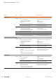
Digital relay output modules
UR20-4RO-SSR-255,
UR20-4RO-CO-255
Status LED Red:
– Error in supply voltage at output current path
– Communication error on the system bus
– There is a new diagnostic message
– Check that the module has been snapped into place
properly
– Check the supply voltage
Digital counter modules
UR20-1CNT-100-1DO,
UR20-2CNT-100
Status LED Red:
– Error in supply voltage at input current path
– Communication error on the system bus
– There is a new diagnostic message
– Check that the module has been snapped into place
properly
– Check the supply voltage
Pulse-width modulation modules
UR20-2PWM-0.5A,
UR20-2PWM-2A
Status LED Red:
– Error in supply voltage at output current path
– Communication error on the system bus
– There is a new diagnostic message
– At least one output overloaded
– Check that the module has been snapped into place
properly
– Check the supply voltage
– Eliminate the overload/short circuit
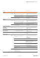
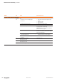
Analogue input modules
UR20-4AI-UI-16, UR20-4AI-UI-12
Status LED Red:
– Error in supply voltage at input current path
– Communication error on the system bus
– There is a new diagnostic message
– Channel error
– Firmware error
– Check that the module has been snapped into place
properly
– Check the supply voltage
– Check channel error
– Check firmware, update firmware as nessecary
Status LED off and all other LEDs red:
Error in the bus coupler power supply
Check the bus coupler supply voltage
Channel LED
1.1 ... 4.1
Red:
– Input signal outside permissible range
– System bus cannot be accessed (e.g. caused by
interruption of the bus coupler power supply)
– Check the input signal
– Check the bus coupler supply voltage