
User manual


LED indicators and troubleshooting | I/O modules
289Manual u-remote1432790000/03/02.2014
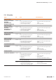
Module LED Status Recommended action
UR20-PF-I
Status LED Red:
– Channel error or communication error on the system
bus, or there is an error in the supply voltage
– Check that the module has been snapped into place
properly
– Check the channel error, check the supply voltage
3.2 Red:
– Supply voltage of the feed in plug <18VDC Check the supply voltage of the feed in plug
3.4 Red:
– Damage of internal fuse – replace module
UR20-PF-O
Status LED Red:
– Channel error or communication error on the system
bus, or there is an error in the supply voltage
– Check that the module has been snapped into place
properly
– Check the channel error, check the supply voltage
4.1 Red:
– Supply voltage of the feed in plug <18VDC Check the supply voltage of the feed in plug
4.2 Red:
– Damage of internal fuse – replace module
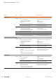
Potential distribution modules
UR20-16AUX-I
UR20-16AUX-GND-I
Status LED Red:
– Error on the supply voltage of the input path
– Check that the module has been snapped into place
properly
– Check the supply voltage
UR20-16AUX-O
UR20-16AUX-GND-O
Status LED Red:
– Error on the supply voltage of the output path
– Check that the module has been snapped into place
properly
– Check the supply voltage
UR20-16AUX-FE
Status LED Off: No supply voltage – Check that the module has been snapped into place
properly
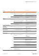
UR20-PF-O-1DI-SIL
Status LED
red
Red:
– Channel error or error in the supply voltage
– Channel error
– Check that the module has been snapped into place
properly.
– Check supply voltage
– Check channel error
– Overload at the OSSD output level – Remove cross connection at OSSD
– External feed-in recognised from field side – Measure voltage at OSSD pin (4.3) vs. GND (4.4).
If a voltage is present, check the wiring!
Attention: safety hazard! Shut down the system and
prevent it from switching on again!
– Internal error detected – Perform a cold start.
If the error has not been xed, send the module to Weidmül-
ler for a technical examination.
– Interruption in one of the two safety loops of a safety
circuit for at least 3 seconds.
– Check safety circuit for interruptions if an interruption of
the safety channel is not part of the application.
– Cross connection between the safety loops for at least
3 seconds.
– Check safety circuit for cross connections.
1.1 Off: Safety circuit 1 interrupted
Yellow: Safety circuit 1 OK
Check safety circuit 1
4.3 Green: Feed-in voltage in valid range