
User manual


Detaileddescriptionsoftheeld-buscoupler| Probus DP eld-bus coupler UR20-FBC-PB-DP
38 1432790000/03/02.2014Manual u-remote
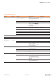
The most signicant digit is set with rotary switchH, the
least signicant digit with rotary switchL . The switches
are labelled in the hexadecimal numbering system (0 to 9,
A=10, B=11, C=12, … F = 15). A hexadecimal to decimal
conversion table is provided in the annex.
Coding: Address = (H*16) + L
H
L
0
1
2
3
4
5
6
7
8
9
A
B
C
D
E
F
0
1
2
3
4
5
6
7
8
9
A
B
C
D
E
F
DefaultsettingUR20-FBC-PB-DP:Address=3
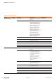
Addressing examples:
H
L
0
1
2
3
4
5
6
7
8
9
A
B
C
D
E
F
0
1
2
3
4
5
6
7
8
9
A
B
C
D
E
F
15
H
L
0
1
2
3
4
5
6
7
8
9
A
B
C
D
E
F
0
1
2
3
4
5
6
7
8
9
A
B
C
D
E
F
112
H
L
0
1
2
3
4
5
6
7
8
9
A
B
C
D
E
F
0
1
2
3
4
5
6
7
8
9
A
B
C
D
E
F
44
ExamplesforaddressingtheUR20-FBC-PB-DP
PROFIBUS address 15: H = 0, L = F
PROFIBUS address 112: H = 7, L = 0
PROFIBUS address 44: H = 2, L = C
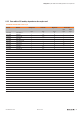
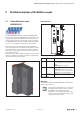
USB
FBC-PB-DP
PWR
SF
BF
MT
Coupler power supply LED
green: supply voltage >18V
red: at least one current path <18V
3.1 Green: Input current path supply voltage >18VDC
3.2 Red: Input current path supply voltage <18VDC
3.4 Red: Internal fuse defective
4.1 Green: Output current path supply voltage >18VDC
4.2 Red: Output current path supply voltage <18VDC
4.4 Red: Internal fuse defective
LEDindicatorsUR20-FBC-PB-DP,errormessages,seeChapter13
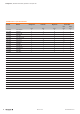
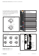
Shield 1
Data B 3
Data A 8
DGND 5
VP +5 V 6
1
5
6
9
X1
24 V DC for output
24 V DC for output
GND for output
GND for output
24 V DC for input
24 V DC for input
GND for input
GND for input
ConnectiondiagramUR20-FBC-PB-DP