
User manual


Detaileddescriptionsoftheeld-buscoupler | Modbus TCP eld-bus coupler UR20-FBC-MOD-TCP
59Manual u-remote1432790000/03/02.2014
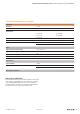
Overview of module IDs
Modul Modul-ID
Digitalinputmodules
UR20-4DI-P 00091F84
UR20-8DI-P-3W 000A1FC1
UR20-16DI-P 00049FC2
UR20-16DI-P-PLC-INT 00059FC2
UR20-2DI-P-TS 0F014700
UR20-4DI-P-TS 0F024700
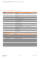
Digitaloutputmodules
UR20-4DO-P 01012FA0
UR20-4DO-P-2A 01052FA0
UR20-8DO-P 01022FC8
UR20-16DO-P 0103AFD0
UR20-16DO-P-PLC-INT 0104AFD0
UR20-4RO-SSR-255 01072FA0
UR20-4RO-CO-255 01062FA0
Digitalcountermodules
UR20-1CNT-100-1DO 08C13800
UR20-2CNT-100 08C33800
Digitalpulsewidthmodulationoutputmodules
UR20-2PWM-PN-0.5A 09084880
UR20-2PWM-PN-2A 09094880
Analogueinputmodules
UR20-4AI-UI-16 040115C4
UR20-4AI-UI-12 041115C4
UR20-8AI-I-PLC-INT 040915C5
Analogueoutputmodules
UR20-4AO-UI-16 050225E0
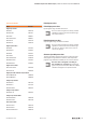
AnalogueinputmodulesDIAG
UR20-4AI-RTD-DIAG 04061544
UR20-4AI-TC-DIAG 04071544
Safe feed-in modules
UR20-PF-O-1DI-SIL 08019E43
UR20-PF-O-2DI-SIL 08029E43
UR20-PF-O-2DI-DELAY-SIL 08039E43
Packedprocessdata
Packedinputprocessdata
Input register range: 0x0000 to 0x01FF
Access to all 512 registers is always possible
regardless of the I/O structure. Unused regis-
ters respond with “0”.
Packedoutputprocessdata
Output register range: 0x0800 to 0x09FF
Access to all 512 registers is always possible
regardless of the I/O structure. Unused regis-
ters send “0” during a read access, write ac-
cesses are ignored.
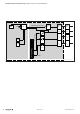
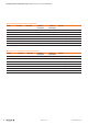
Structure of packed process data
The byte granularly packed process data contains all input
data (register range 0x0000 to 0x01FF) and output data
(register range 0x0800 to 0x09FF) of the u-remote station.
Process data is mapped according to
the modules are arranged. To avoid larger
gaps in the process data, the different modules
should be arranged in an optimal manner.