
User manual

Detaileddescriptionsoftheeld-buscoupler| Modbus TCP eld-bus coupler UR20-FBC-MOD-TCP
62 1432790000/03/02.2014Manual u-remote
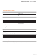
0x1000 – 0x1006Coupleridentier
The identier is the “product designation”: UR20-FBC-MOD.
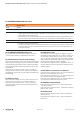
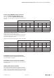
0x100C Coupler status
Bit Name Meaning
0 Summarized module diagnosis A diagnosis is available on at least one module with diagnostics functionality.
1 Errorbit 1 Reserve bit 1, currently not used
2 Errorbit 2 Reserve bit 2, currently not used
3 Systembus error Error on system bus. Communication with the connected modules is disrupted.
4 Errorbit 4 Reserve bit 4, currently not used
5 Errorbit 5 Reserve bit 5, currently not used
6 I/O-Conguration error Differing conguration. The module list has changed. The list of congured modules (reference mod-
ule list 0x2800 – 0x287F) differs from the module list detected by the coupler (current module list
0x2A00 – 0x2A7F).
7 Master conguration error Master conguration error. The list of congured modules (reference module list 0x2800 – 0x287F) differs
signicantly from the module list detected by the coupler (current module list 0x2A00 – 0x2A7F). Process
data cannot be exchanged with the modules.
8 Errorbit 8 Reserve bit 8, currently not used
9 Errorbit 9 Reserve bit 9, currently not used
10 Force mode active Force mode was activated via the web server. Forced channels do not exchange data with the master.
11 Errorbit 11 Reserve bit 11, currently not used
12 Errorbit 12 Reserve bit 12, currently not used
13 Voltage U
OUT
error Error in the supply voltage of outputs
14 Voltage U
IN
error Error in the supply voltage of system and inputs
15 Errorbit 15 Reserve bit 15, currently not used
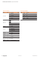
0x1010Processimagelengthinbitsforthe output mod-
ules
0x1011Processimagelengthinbitsforthe input modules
0x1017Register–mappingrevision
Version of the register structure