
User manual


Detailed descriptions of I/O modules | Digital pulse width modulation output module UR20-2PWM-PN-0.5A
163Manual u-remote1432790000/03/02.2014
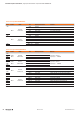
2PWM
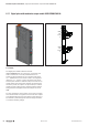
Module status LED
Green: Communication over the system bus
Red: Collective error diagnostic
1.1
Yellow: PWM output 0 = 100 %, p- or n-switching
Yellow ashing at 2Hz: PWM output 0 is > 0 and < 100 %,
p- or n-switching
3.1
Yellow: PWM output 1 = 100 %, p- or n-switching
Yellow ashing at 2Hz: PWM output 1 is > 0 and < 100 %,
p- or n-switching
LEDindicatorsUR20-2PWM-PN-0.5A,errormessagesseeChapter13
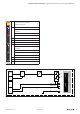
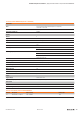
GND
PWM0
PWM1
1
3
1
3
1
3
PWM0
GND
24 V DC
FE
PWM1
GND
24 V DC
FE
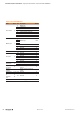
System
bus
U
SYS
U
IN
U
OUT
µC
24 V DC⎽OUT
GND⎽OUT
FE
1
3
UR20 2PWM-0,5A
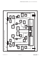
BlockdiagramUR20-2PWM-PN-0.5A