
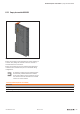
User manual
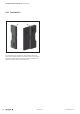
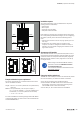


7.4 Codingthemodule
In order to prevent an electronic module being mismated, the
modules can be coded by the customer. Coding is carried
out by two small components: the orange coding socket and
the black coding pin. Three codings can be applied to each
basic module. Suggestions for the appropriate coding can be
found in the annex.
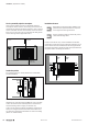
Codingsocketandcodingpin
▶ Open the connection frame and remove the electronic
unit (see Chapter 7).
▶ Place the coding sockets (orange) in the coding ports on
the inside of the basic module.
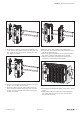
Basicmodulewithinsertedcodingsockets
Each coding socket has one pointed and three rounded
corners. The arrangement of the three sockets in the basic
module allows for 4
3,
i.e. 64, possible combinations.
▶ If necessary, you can rotate the inserted coding sockets
into the required position using a 3-mm screwdriver.
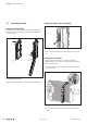
▶ Insert a black coding pin to the stop in each coding
socket.
A small orange corner will now be visible on each coding
unit, which allows the coding state to be identied.
Codingsocketwithinsertedcodingpin
▶ Put the electronic module back into position.
The coding pin now engages securely in the electronic mod-
ule. If the electronic unit has to be removed again, it can sub-
sequently only be re-inserted back into the correspondingly
coded basic module.
If the electronic module is replaced by a new module, this
must be tted with new coding pins.
Installation | Coding the module
239Manual u-remote1432790000/03/02.2014