
User manual


Installation | Wiring
240 1432790000/03/02.2014Manual u-remote
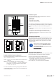
7.5 Wiring
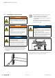
WARNING
Explosion risk!
▶ Before assembly, make sure that there is
not a potentially explosive atmosphere!
▶ For applications in potentially explosive
atmospheres, observe the installation and
construction requirements of EN60079-
15 and/or country-specific regulations.
WARNING
Dangerous contact voltage!
▶ Carry out assembly and wiring work on
the u-remote station only when the power
supply is disconnected.
▶ Make sure that the place of installation
(switch cabinet etc.) has been discon-
nected from the power supply!
WARNING
Safety functions of PF-O-xDI-SIL mod-
ules can be impaired!
When PF-O-xDI-SIL modules are installed in
the u-remote station, please observe the fol-
lowing points:
▶ Please use wire-end ferrules in combina-
tion with flexible/multi-conductor cables.
▶ Ensure that for safety inputs in the config-
uration without test pulses the cabling
prevents external short circuits (see
DINENISO13849-2 Table D.4).
Once the u-remote station has been mechanically installed,
the wiring can be carried out in accordance with the wir-
ing plan. Lines with a cross-section measuring between
0.14mm² and 1.5mm² can be connected.
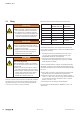
We recommend using the following wire-end ferrules:
Cross-section Weidmüller order no.
Weidmüller colour code
Weidmüller order no.
DIN colour code
0,14 mm² 9028240000
0,25 mm² 9025760000
0,34 mm² 9025770000
0,50 mm² 9025870000 9019020000
0,75 mm² 9025860000 9019050000
1,00 mm² 9025950000 9019100000
1,50 mm² 0635100000 9019130000
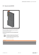
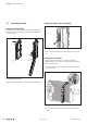
Wire-endferrulesforthewiring
The external dimensions of the crimped wire-end ferrules
must conform with IEC-60947-1. We recommend the follow-
ing tools for crimping:
– Crimping tool for wire-end ferrules from 0.25mm² to
1.5mm² with a trapezoidal indentation crimp, type:
PZ6/5 ZERT (Order No. 9017900000)
– Crimping tool for wire-end ferrules from 0.14mm² to
0.75mm² with a trapezoidal crimp, type: PZ 1.5 ZERT
(Order No. 9017310000)
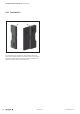
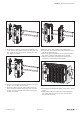
u-remote modules and bus couplers are equipped with the
“PUSH IN” connector system. Single-strand and ne-strand
lines with wire-end ferrules can be inserted without the need
for a tool.
▶ Each cable must be the optimal length so that the bend-
ing radii observe the manufacturer's specifications.
▶ Strip the insulation from the lines to a length of approx.
10mm ±1mm, even if you are using wire-end ferrules. If
you use wire-end ferrules with plastic collars, strip the
wires to 12mm ±1mm.
▶ Connect all lines according to wiring diagram.
For the usage and handling of the “PUSH-IN” system, see
Section 8.5.