
User manual


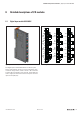


Detaileddescriptionsoftheeld-buscoupler| Modbus TCP eld-bus coupler UR20-FBC-MOD-TCP
66 1432790000/03/02.2014Manual u-remote
0x2A00 – 0x2A7FCurrentmodulelist
Each module identier is made up of 4 bytes (2 registers)
(see the Overview of module IDs). The modules that were
connected when the coupler was started are entered here.
To simplify conguration, the current module list can be cop-
ied into the reference module list.
0x8000 – 0x87FFProcessdatainputs
For each module a data length of 64 Byte (32 Register) is
reserved.
Example: Module 3 starts at address 0x8040.
0x9000 – 0x97FFProcessdataoutputs
For each module a data length of 64 Byte (32 Register) is
reserved.
Example: Module 3 starts at address 0x9040.
0xA000 – 0xA7FFDiagnostics
For each module a diagnostics data length of 64 Byte (32
Register) is reserved.
Example: Module 3 starts at address 0xA040.
In case of a diagnostics message, the 47 bytes of the mod-
ule diagnosis are entered here from the corresponding tables
(see the table of diagnostic data in the corresponding mod-
ule description in the Module chapter).
If a 1 is set in register 0x1134, reading out the correspond-
ing diagnosis results in a conrmation of the alarm.
0xB000 – 0xB7FFProzessalarms
For each module a process alarm data length of 64 Byte (32
Register) is reserved.
Example: Module 3 starts at address 0xB040.
In case of a process alarm, the 4 bytes of the module are
entered here from the corresponding table (see the table of
process alarms in the corresponding module description in
the Module chapter).
0xC000 –0xC7FFParameters
For each module a parameter data length of 64 Byte
(32Register) is reserved.
Example: Module 3 starts at address 0xC040.
To parameterise a module, use the web server (see the Web
Server chapter). After parameterisation, you can read out the
parameter set for the corresponding module using the mod-
bus command function code 3 Read Holding Registers You
can copy this data into your project.