
User manual


Detailed descriptions of I/O modules | Analogue input module UR20-4AI-UI-12
179Manual u-remote1432790000/03/02.2014
6.20 AnalogueinputmoduleUR20-4AI-UI-12
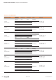
AnalogueinputmoduleUR20-4AI-UI-12(OrderNo.1394390000)
The analogue input module UR20-4AI-UI-12 can record up
to 4analogue sensors with ±10V, ±5V, 0 ... 10V, 0 ... 5V,
2 ... 10V, 1 ... 5V, 0 ... 20mA or 4 ... 20mA. The resolution is
12 bits per channel. Sensors can be connected to each con-
nector in a 2- or 3-wire connection. The measurement range
is dened using parameterisation. A status LED is assigned
to each channel. The module electronics supply the connect-
ed sensors with power from the input current path (U
IN
).
The inputs are protected against voltage surges and overcur-
rent. Voltages that exceed ±30V may cause the destruction
of the module. As a protection against overcurrent, the mod-
ule temporarily switches to voltage mode.
1
2
3
4
2
1
3
4
1
2
3
4
2
4
3
1
2
4
3
1
4AI-UI-12
1
2
3
4
2
1
3
4
1
2
3
4
2
4
3
1
2
4
3
1
AI0
0 V
24 V DC
FE
AI1
0 V
24 V DC
FE
AI2
0 V
24 V DC
FE
AI3
0 V
24 V DC
FE
AI0
0 V
↑U, I
↑U, I
↑U, I
↑U, I
FE
AI1
0 V
24 V DC
FE
AI2
0 V
24 V DC
FE
AI3
0 V
24 V DC
FE
↑I
↑I
↑I
↑I
4AI-UI-12
24 V DC
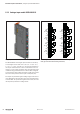
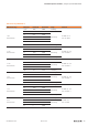
ConnectiondiagramUR20-4AI-UI-12(left3/4-wiresensorwithsensorwiringviaelec-
tronics,right:2-wiresensorwithsensorwiringviaelectronics)