
User manual

Detaileddescriptionsoftheeld-buscoupler | Modbus TCP eld-bus coupler UR20-FBC-MOD-TCP
53Manual u-remote1432790000/03/02.2014
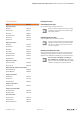
USB
PWR
SF
BF
MT
LINK1
ACT1
LINK2
ACT2
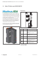
FBC-MOD
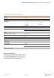
Coupler power supply LED
green: supply voltage >18V
red: at least one current path <18V
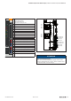
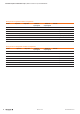
3.1 Green: Input current path supply voltage >18VDC
3.2 Red: Input current path supply voltage <18VDC
3.4 Red: Internal fuse defective
4.1 Green: Output current path supply voltage >18VDC
4.2 Red: Output current path supply voltage <18VDC
4.4 Red: Internal fuse defective
LEDindicatorsUR20-FBC-MOD-TCP,errormessages,seeChapter13
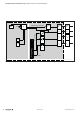
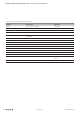
TD+ 1
TD– 2
RD+ 3
RD– 6
TD+ 1
TD– 2
RD+ 3
RD– 6
24 V DC for output
24 V DC for output
GND for output
GND for output
24 V DC for input
24 V DC for input
GND for input
GND for input
X1
X2
ConnectiondiagramUR20-FBC-MOD-TCP
ATTENTION
Risk of material damage!
In the case of a maximum power supply of >8 A and a
maximum temperature of > +55 °C, all four contacts must
be connected with 1.5mm² wiring!