
User manual


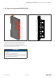
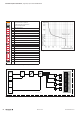

Detailed descriptions of I/O modules | Digital output module UR20-16DO-P-PLC-INT
121Manual u-remote1432790000/03/02.2014
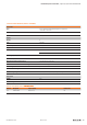
TechnicaldataUR20-16DO-P-PLC-INT(OrderNo.1315270000)
System data
Data
Process, parameter and diagnostic data depend on the coupler used,
see the table in Section 4.10.
Interface
u-remote system bus
System bus transfer rate
48 Mbps
Outputs
Number
16
Type of load
ohmic, inductive, lamp load
Response time
max. 100 µs high ; max. 250 µs low
Max. output current
per channel 0.5A
per module 8 A (2 A with power supply via a at ribbon
cable)
Breakingenergy(inductive)
150mJ
Switchingfrequency
Resistive load (min. 47 Ω) 1kHz
Inductive load (DC 13) 2Hz
Lamp load (12W) 1kHz
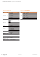
Actuator connection
PLC interface unit
Short-circuit-proof
yes
Protectivecircuit
Constant current with thermal switch-off and automatic restart
Responsetimeofthecurrentlimitingcircuit
< 100µs
Modulediagnosis
yes
Individualchanneldiagnosis
no
Reactionless
yes
Supply
Supplyvoltage
24V DC +20 %/-15 %
Currentconsumption(I
IN
inthepowersegmentofthefield-bus
coupler),typ.
8mA
Currentconsumption(I
IN
intherespectivepowersegment)
20mA + load, power supply through plug-in connector 4
Connection data
Type of connection
“PUSH IN”
Line connection cross-section
Single-wired 0.14 – 1.5mm
2
(AWG 16 – 26)
Fine-wired 0.14 – 1.5mm
2
(AWG 16 – 26)
I/O connector
20-pole ribbon cable connection
General data
Weight
82g
Foradditionalgeneraldata,seeSection3.4