
User manual


System overview | Mechanical xing elements
15Manual u-remote1432790000/03/02.2014
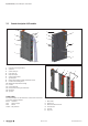
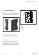
3.5 Mechanicalxingelements
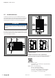
The station is xed in the installation position by an end
bracket at either side. The last I/O module is protected
against dust by a cover plate, into which the second end
bracket is inserted and screwed to the mounting rail. Every
u-remote coupler is supplied with a termination kit.
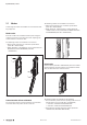
1 2
u-remotestationfixingelements
1 End bracket (left end, on the coupler side)
2 Terminatio n kit with end plate and end bracket (right end)
For vertical installation, a special end bracket (Order No.
1162600000 WEW 35/1 SW) must also be installed below
the station.
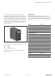
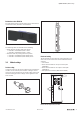
3.6 Type plate
Each eld-bus coupler and each module features a type
plate, which includes identication information, the key tech-
nical specications and a block diagram. In addition, a QR
code allows for direct online access to the associated docu-
mentation. The software for reading the QR code must sup-
port inverted QR codes. A breakdown of the serial numbers
can be found in the table provided in the annex.
3
1
5
4
2
6
Typeplate(exampleofUR20-4DI-P)
1 Product number
2 Serial number
3 Manufacturing code
4 ATEX marking
5 QR code
6 Block diagram