
User manual


Conguration | Use in a potentially explosive atmosphere
21Manual u-remote1432790000/03/02.2014
For vertical installation interchange height and width. When
calculating the width, 4,5mm / 0.18" for the must be added
for the end bracket MEW35/1.
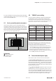
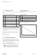
4.3 Use in a potentially explosive atmosphere
If the u-remote station is used in a potentially explosive
atmosphere rated as Zone 2, the housing must meet the re-
quirements of explosion protection type Exn or Exe and pro-
tection class IP54. Sensors and actuators that are located in
Zone 2 or in a safe zone can be connected. All cable glands
on the housing must be approved for Exe.
IP54
Zone 2
safe area
no ex-approval
u-remote
II 3G Ex nA
II 3G Ex nA nC
Use in a potentially explosive atmosphere
ATEXmarking
II 3 G Ex nA IIC T4 Gc
WI 13ATEX0002X
Ta: -20 °C ... +60 °C
4.4 “PUSHIN”systemcabling
u-remote modules and eld-bus couplers are equipped with
the “PUSH IN” connector system. Single-strand and ne-
strand lines with wire-end ferrules can be inserted without
the need for a tool. Lines with a cross-section measuring be-
tween 0.14 mm
2
and 1.5mm
2
can be connected.
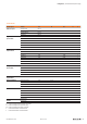
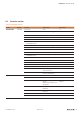
We recommend using the following wire-end ferrules:
Cross-section
AWG
Weidmüller order no.
Weidmüller colour code
Weidmüller order no.
DIN colour code
0,14 mm² 26 9028240000
0,25 mm² 24 9025760000
0,34 mm² 22 9025770000
0,50 mm² 20 9025870000 9019020000
0,75 mm² 18 9025860000 9019050000
1,00 mm² 17 9025950000 9019100000
1,50 mm² 16 0635100000 9019130000
Wire-endferrulesforthewiring
The external dimensions of the crimped wire-end ferrules
must conform with IEC-60947-1. For crimping, we recom-
mend crimp shape A and the following tools:
– Crimping tool for wire-end ferrules from 0.25mm² to
1.5mm² (AWG 24 to 16) with a trapezoidal indentation
crimp, type: PZ6/5 ZERT (Order No. 9017900000)
– Crimping tool for wire-end ferrules from 0.14mm² to
0.75mm² (AWG 26 to 18) with a trapezoidal crimp, type:
PZ 1.5 ZERT (Order No. 9017310000)
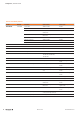
4.5 Current demand and power supply
The u-remote system uses three internal current paths:
The I
SYS
system current path supplies the communication
part of the I/O modules; it is fed from the coupler input sup-
ply and cannot be interrupted by any module. The maximum
current-carrying capacity of II
SYS
allows a u-remote station to
be expanded with a maximum of 64 active modules without
having to refresh the power.
The I
IN
input current path supplies the input circuit of the
input modules as well as the connected II
S
sensors. The cur-
rent must be refreshed with UR20-PF-I (power feed in) mod-
ules as required. These UR20-PF-I modules isolate the input
current path towards the left (towards the coupler), and as a
result start a new electricity segment towards the right.