
User manual

Conguration| Example calculation for the power supply
24 1432790000/03/02.2014Manual u-remote
4.6 Example calculation for the power supply
The power supply must be calculated individually for each
station installation. Therefore the simultaneity factor g and
the current demand of each module, as well as the devices
to be connected must be established (see the example calcu-
lation table).
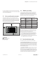
In the example station, a PROFINET-IRT coupler is cong-
ured with four UR20-4DI-P modules and eight UR20-8DO-P
modules. The cumulative current demand for each module is
now calculated to determine whether and at which point a
UR20-PF-I power-feed module must be positioned to refresh
the current path. A power-feed module must always be used
where the current demand exceeds 10 A.
The power refresh must be separately calcu-
lated for the input and output current paths.
The system voltage need not be considered
during this step.
Calculation of the current demand for the input cur-
rent
The current consumption of the eld-bus coupler must be
considered for the main power supply, and the sum of
consumption values is multiplied by the simultaneity factor g
for each following module:
I
SYS
coupler
+ (I
SYS
+ I
IN
)+ (I
S
x g) module 1
+ (I
SYS
+ I
IN
)+ (I
S
x g) module 2
+ ∑((I
SYS
+ I
IN
)+ (I
S
x g)) modules 3 to 4
= Cumulative current demand
I
SYS
Current consumption from the system current path
I
IN
Current consumption from the input current path
I
S
Power supplies for the connected sensors
In the case of an additional power supply (power refresh)
with a UR20-PF-I power-feed module, only the sensor power
supplies and the module current consumption have to be
considered:
((I
IN
+ I
S
module x) x g)
+ ((I
IN
+ I
S
module y) x g)
+ ∑((I
IN
+ I
S
) x g) n modules
= Cumulative current demand
I
IN
Current consumption from the input current path
I
S
Power supplies for the connected sensors
Calculation of current demand for the output current
The current consumption of each module and the current
demand of the connected actuators must be considered for
the output current. There is no difference in the calculation
of the main power supply and power refresh:
(I
OUT
+ (I
L
x g) module 1
+ (I
OUT
+ (I
L
x g) module 2
+ ∑(I
OUT
+ (I
L
x g)) n modules
= Cumulative current demand
I
OUT
module current consumption from the output current path
I
L
Current demand of the connected actuators
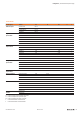
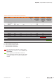
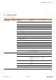
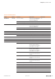
Example:
The values in the following table are used to calculate the
current demand of the example station (cumulative for each
module). The input current is:
Module1:
I=0.116 A + (0.008 A + 0.012 A) + (0.06 Ax1)= 0.196A
Module2:
I=0.196 A+ (0.008 A + 0.012 A) + (0.06 Ax1)= 0.276A
The values for the other modules are calculated accordingly.
The result shows that the accumulated value for up to 12
modules remains under 10 A, and therefore a power-feed
module need not be used for the input current path.
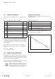
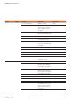
Results for the output current path:
Module 5:
I=0.015 A+(0.5A x2)=1.015A
Modul6 6:
I=1.015 A+(0.015 A+(0.5A x4)=3.03A
Module10:
I=6.175A +(0.015A +(0.5 Ax4)=8.19A
Module11 (without power refresh):
I=8.19 A+(0.015 A+(0.5 Ax4)=10.205A
Therefore the available 10 A would be exceeded. As a result,
a PF-O power-feed module must be positioned e 11th mod-
ule, which will supply anocalculation of current consumption
is repeated for each power-feed module. Unused current
values may not be included.
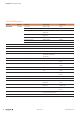
Module11 (as per PF-O):
I=(0.015 A+(0.5 Ax4)=2.015A
Module 12 (as per PF-O):
I = 2.015A (0.015 A + (0.5 A x 4) = 4.030A