
User manual

Earthingandshielding| Earthing of shielded cables
244 1432790000/03/02.2014Manual u-remote
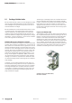
Effectiveshielding
It is important that the shielding is not positioned on the
earth of the connected component, but on the protective
earth. In the case of components that are installed in a metal
housing, the shielding must be positioned to this housing. If
no earthed housing is available, the shielding is positioned
on a separate earth.
When installing ground connections on shielding, it is gen-
erally also important that no earth loops are created. The
smaller the earth loop, the less the danger of the induction
of interference voltages. It is therefore most suitable to have
apurely neutral-point installation.
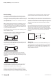
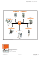
The following sketches show the possible shielding connec-
tions to protective earth.
A one-sided connection of the shielding protects against
capacitive coupling of interference voltages.
System 1 System 2
1HF1MM
∬
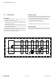
If you use a two-sided shielding connection, make sure that
compensating current (different earth potentials) does not
ow through the cable shield.
System 1 System 2
If you wish to avoid the disadvantages associated with
creating an earth loop with two-sided shields, it is recom-
mended you connect one side of the shield through ahigh
impedance.
System 1 System 2
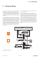
For longer lengths of shielded cables, such as if a sensor
must be added to a control panel, a potential difference
between both end points must not be ignored.
However, such shield conductors are relatively expensive
and also require more time in working with them. Another
possibility would be to place an additional voltage equalising
cable between the measurement location and the control
panel. The shield can then be hooked up on both sides.
A high-impedance earth connection is also another option.
In the control panel, the shield is then connected to the earth
potential, and the shield has a high-impedance connection to
earth at the measurement location via a gas discharge tube.
This solves the problem of a potential transfer and 50-Hz
humming.
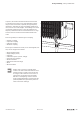
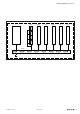
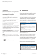
For non-isolated measurement locations, two gas discharge
tubes must be installed. One connects the shield to earth,
and the other connects it to the non-isolated measurement
location. This method prevents a galvanic coupling between
the measurement circuit and the earthed measurement
location.
Shield connection
Earth
Measuring point
1 4
5
TS
23
IN
OUT
Summary
Earthing is a key element for the reliable functioning of an
electrical system in the event of interference. In this regard,
HF-related aspects must be taken into consideration. Only
the proper use of materials and a well thought-out circuit
design will lead to success.