
User manual

Earthingandshielding| Electromagnetic compatibility (EMC)
248 1432790000/03/02.2014Manual u-remote
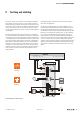
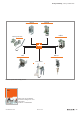
8.3 Electromagneticcompatibility(EMC)
u-remote products completely meet EMC requirements. EMC
planning, however, is necessary prior to installation.
Aspects to consider include all potential interference sources
such as galvanic, inductive and capacitive couplings, as well
as radiation couplings.
EnsuringEMC
To ensure EMC, the following basic principles must be ob-
served during installation of the u-remote modules:
– Proper, extensive earthing of inactive metal parts
– Correct shielding of cables and equipment
– Proper layout of wires – cabling
– Creation of a uniform reference potential and earthing
ofall electrical equipment
– Special EMC measures for special applications
(e.g. frequency converters, servo drives)
– Contactors and relay coils must be equipped with the
corresponding interference suppressors
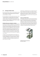
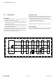
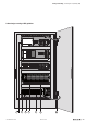
Earthingofinactivemetalparts
The earthing of all inactive metal parts reduces the inuence
of coupled interference. For this purpose, all inactive metal
parts (such as switch cabinets, cabinet doors, support beams,
mounting plates, DIN rails, etc.) must be con nected to each
other over a large surface area with low impedance, whereby
a uniform reference potential is ensured for all control unit
elements.
Required measures:
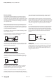
– Removal of the insulating layer around screw connec-
tions. Protection of connection points against corrosion
– Connection of moving earthed components (cabinet
doors, separated mounting plates, etc.) through short
earthing straps with large surfaces
– When possible, avoid using aluminium parts, because
aluminium oxidises easily and in this respect is unsuited
for earthing
PEconnection
The connection from earth to the PE (protective earth) con-
nection must be done centrally.
WARNING
Possible danger to life!
In the event of a fault, the earth must never
take on a dangerous contact voltage, which is
why it must be connected to a PE conductor.
Unearthed operation
In the event of unearthed operation, the corresponding safe-
ty regulations must be observed.
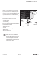
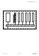
DIN rails
Notes concerning the use of DIN rails:
– Large-surface, low-impedance attachment on the mount-
ing plate and corresponding contact with the carrier sys-
tem using screws or rivets
– Proper earthing
– Use corrosion-proof DIN rails
– Remove the insulating layer on painted, anodised or insu-
lated metal components in the area around the connec-
tion point
– Protect the connection point against corrosion (e.g. using
grease; Attention: only use grease suitable for the pur-
pose)