
User manual
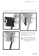

Insertingthenewelectronicunit
▶ Fold the connector frame back so that it closes and clicks
into place.
▶ In case of replacement during operation: Pay attention to
the collective error LED (SF) on the field-bus coupler.
Only when this doesn't light up any more, the new elec-
tronic unit has been recognised and the next electronic
unit is able to be pulled out.
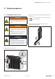
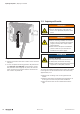
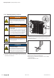
11.3 ReplacinganI/Omodule
WARNING
Explosion risk!
▶ Prior to starting work, make sure that
there is not a potentially explosive atmos-
phere!
WARNING
Dangerous contact voltage!
▶ Prior to removing modules, the u-remote
station must be completely de-energised
(supply of the field bus coupler and all
external feed-in).
▶ Make sure that the place of installation
(switch cabinet etc.) has been discon-
nected from the power supply.
ATTENTION
The product can be destroyed by elec-
trostatic discharge!
The components in the u-remote series can
be destroyed by electrostatic discharge.
▶ Please make sure that personnel and work
equipment are adequately earthed!
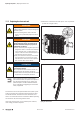
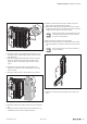
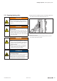
To remove an individual module from the station, all modules
to the right of it and the termination kit must be moved by
approximately 5cm.
▶ Unfasten the mounting screw on the right-hand end
bracket.
▶ Slide the end bracket and end plate approximately 5cm
to the right or remove both parts from the DIN rail.
▶ Open the release lever on the module furthest to the
right.
Replacingcomponents| Replacing an I/O module
276 1432790000/03/02.2014Manual u-remote