
User manual
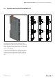


Detailed descriptions of I/O modules | Digital input module with time stamp UR20-2DI-P-TS
88 1432790000/03/02.2014Manual u-remote
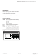
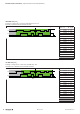
Example for the mode of operation
The following example shows the sequence in which ETS en-
tries are stored. The input channels are predened as follows:
DI 0 and DI1: time stamp at edge 0-1 enabled
DI 0 and DI1: time stamp at edge 1-0 enabled
The ETS entries available at time “t” are designated by the
green area in the diagram. ETS entries that are not (or no
longer) available have a grey background
New ETS entries are always entered starting
at address + 0 and already existing ETS en-
tries are each shifted by 4 bytes.
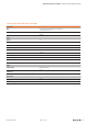
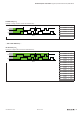
Process image is empty at t
0
00
DI 0
DI 1
65535
µs
t
0
Address
PII RN ETS_US
+0
+4
+8
+12
+16
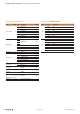
1st ETS entry at t
1
A rising 0-1 edge on DI 0 causes the 1st ETS entry at ad-
dress + 0.
00
DI 0
DI 1
65535
µs
t
1
Address
PII RN ETS_US
+0 00000001 0 16875
+4
+8
+12
+16
2nd ETS entry at t
2
A rising 0-1 edge on DI 1 causes the 2nd ETS entry at ad-
dress + 0. The 1st ETS entry is shifted by 4 bytes.
00
DI 0
DI 1
65535
µs
t
2
Address
PII RN ETS_US
+0 00000011 1 28344
+4 00000001 0 16875
+8
+12
+16