
User manual


Detailed descriptions of I/O modules | Digital output module UR20-4DO-PN-2A
107Manual u-remote1432790000/03/02.2014
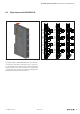
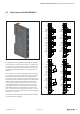
DigitaloutputmoduleUR20-4DO-PN-2A(OrderNo.1394420000)
The digital output module UR20-4DO-PN-2A can control up
to 4 actuators each with a maximum of 2 A. 1 actuator can
be connected to each connector in a 2-wire or 3-wire + FE
connection. A status LED is assigned to each channel. The
outputs are supplied with power from the output current
path (U
OUT
).
Each channel can be switched between positive and nega-
tive switching. This allows, among other things, a switch in
rotational direction if an DC motor is connected between
two outputs. For this purpose, an output byte is reserved for
the physical outputs, and each channel is assigned two bits
in this byte. The switching characteristics of each output
are set in the low nibble of the byte. If a bit is set, the cor-
responding channel has positive switching, if it is 0 then
it has negative switching. The outputs are switched in the
high nibble. Example: If you write the value 185decimal
(10111001binary) in the output byte, Channel1 is set to
24V, Channel 2 is set to GND, Channel3 is deactivated and
Channel4 is set to 24V.
The module is protected against external voltages between
0V and the operating voltage.
1
2
3
4
2
1
3
4
1
2
3
4
2
4
3
1
2
4
3
1
4DO·P-2A
DO0
GND
24 V DC
FE
DO1
GND
24 V DC
FE
DO2
GND
24 V DC
FE
DO3
GND
24 V DC
FE
1
2
3
4
2
1
3
4
1
2
3
4
2
4
3
1
2
4
3
1
4DO·P-2A
24 V DC
DO3
DO2
DO1
DO0
GND
GND
GND
GND
24 V DC
24 V DC
24 V DC
1
2
3
4
2
1
3
4
1
2
3
4
2
4
3
1
2
4
3
1
4DO·P-2A
DO3
DO2
DO1
DO0
GND
GND
GND
GND
1
2
3
4
2
1
3
4
1
2
3
4
2
4
3
1
2
4
3
1
4DO·P-2A
DO0
GND
24 V DC
FE
DO1
GND
24 V DC
FE
DO2
GND
24 V DC
FE
DO3
GND
24 V DC
FE
M
M
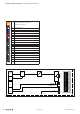
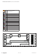
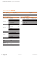
ConnectiondiagramUR20-4DO-PN-2A
6.9 DigitaloutputmoduleUR20-4DO-PN-2A