
User manual
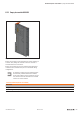
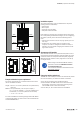
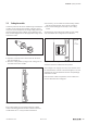

AttachingthebuscouplertotheDINrail
▶ Slide the bus coupler to the left until it completely con-
nects with the end bracket. At the same time, press the
bus coupler as close as possible to the DIN rail so that
the coupler is not tilted.
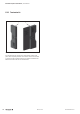
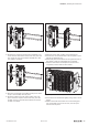
Slidingthebuscouplerintoposition
▶ Place the first module on the DIN rail and press it down
firmly. It must audibly click into place.
▶ Slide the module to the left until it audibly clicks into
place on the bus coupler. At the same time, press the
module as close as possible to the DIN rail so that the
module is not tilted.
Slidingthemoduleintoposition
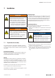
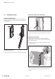
▶ Attach all of the other modules as described above.
▶ Connect the second end bracket to the end plate as spec-
ified by the alignment pins.
▶ Place both parts on the DIN rail on the right-hand side of
the station so that the end bracket faces outwards.
▶ Slide the end bracket and end plate to the left until it
completely connects with the last module.
Slidingtheendplatewithendbracketintoposition
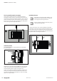
▶ Screw down the end bracket tightly (using a 3-mm screw-
driver).
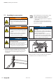
▶ Make sure that all release levers are in the locking posi-
tion as standard. If this is not the case, click the open
release lever into place.
Installation | Assembling the u-remote station
237Manual u-remote1432790000/03/02.2014