
User manual


Detaileddescriptionsoftheeld-buscoupler| Modbus TCP eld-bus coupler UR20-FBC-MOD-TCP
64 1432790000/03/02.2014Manual u-remote
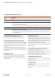
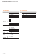
0x1130MODBUSCONNECTIONmoderegister
Bit Name/Description
2 to 15 reserved
1 MB_ImmediateWritePermission
– 0: during the rst write access, write authorisation is requested for the corresponding modbus connection. If this is not successful, an
exception response with the exception code 0x01 is generated. If it is successful, the write access is executed and write authorisation
remains in effect until the end of the connection.
– 1: write authorisation for the corresponding modbus connection is already requested when the connection is being established. As a re-
sult, the rst modbus connection receives the write authorisation, and nothing happens for all those that follow (as long as Bit 0 = 1).
0 MB_OnlyOneWritePermission
– 0: all modbus connections have write authorisation
– 1: in all cases only one modbus connection can be assigned write authorisation. Once assigned, write authorisation is retained until there
is a disconnect. After the connection that has write authorisation is disconnected, the next connection which attempts write access
receives write authorisation.
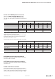
0x1131MODBUSCONNECTIONtimeoutinsec.
This register determines how long a modbus connection
must be inactive before it is ended with a disconnect.
0x1132Checkreferencelistpriortodataexchange
If the value in register 0x1132 is set to 0, the data exchange
begins without checking the reference module list (0x2800
and the following) against the current module list (0x2A00
and the following). The reference module list must also not
be described.
If the value in in register 0x1132 is set to 1, the data ex-
change only starts if the reference module list (0x2800 and
the following) matches the current module list (0x2A00 and
the following).
0x1133Processalarm
If the value in this register is set to 0, process alarms are re-
ported, but it is not necessary to conrm or read them.
If the value in this register is set to 1, process alarms are
reported and they must be conrmed by reading the corre-
sponding register.
0x1134Diagnosticalarm
If the value 0 is set in this register, the diagnostic alarm is
deactivated. Pending diagnostics do not have any effect on
the exchange of process data and must not be conrmed.
They are, however, displayed locally on the UR20 hardware
with red LEDs (SF and module) and also can be read in the
module-specic diagnostic registers 0xAXXX.
If the value in this register is set to 1, diagnostics alarms are
reported, and they must be conrmed by reading the corre-
sponding register.
0x1135 Field bus or reference list error behaviour
If the value in this register is set to 0, in case of a eld bus or
reference list error all outputs are set to 0.
If the value in this register is set to 1, in case of a eld bus er-
ror all outputs are set to the substitute values.
If the value in this register is set to 2, in case of a eld bus er-
ror all outputs are held at the last process value.
0x1136 Module removal behaviour
If the value in this register is set to 0, the exchange of pro-
cess data continues.
If the value in this register is set to 1, the behaviour during a
eld bus error is used.
0x1137 Data format
If the value in this register is set to 0, data is transferred in
Motorola format.
If the value in this register is set to 1, data is transferred in
Intel format.