
User Documentation

Weidmüller Interface GmbH Co. KG; Klingenbergstraße 16, 32758 Detmold-Germany
A2C 2.5
A2C 2.5 PE
550 V
20 A / ΔT
≤
40 K
19 A / ΔT
≤
40 K
0,8 m
Ω
2,5 mm²
2,5 mm²
0,5 - 2,5 mm²
0,5 - 2,5 mm²
0,5 - 2,5 mm²
0,5 - 2,5 mm²
0,5- 2,5 mm²
0,5 - 2,5 mm²
28 - 12 AWG
28 - 12 AWG
10 mm
10 mm
440 V
550 V
352 V
550 V
220 V
- Stripping length
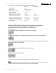
IECEx / ATEX Terminal and Cross-Connection Arrangements:
Information for further cross-connector arrangements will be provided on request.
A - Continuous no difference between one or two cross connections
C - Adjacent – separated by an end plate no difference between one or two cross-connections
D - Intermediate - bridging one or more unconnected terminals (e.g. every 3rd terminal) no difference
between one or two cross connections
F - Next to a protective conductor terminal (earth) with end plate
H - Cross-connection with twin parallel
Application Case
Max voltage data according to IEC/EN 60079-7 in conjunction with
protective earth terminal blocks of the A-Series, (increased safety "eb"):
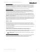
Note:
If smaller cross sections than the rated cross section are used, the belonging lower current has to be laid
down in the IECEx/EC-Type Examination Certificate of the complete apparatus.
- Rated current with ZQV
- Rated voltage
- Rated current
Technical data according to IEC/EN 60079-7 (increased safety "eb"):
- Conductor cross section solid
- Rated conductor cross section
- Conductor cross section flexible
- Contact resistance
with rated conductor, 2.5 mm²
- Conductor cross section stranded
- cross section, American Wire Gauge
Version: A2C 2.5; 10652170 Index: 04 Date: 06.2019
2