
User Documentation
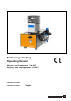


Abisolier- und Crimpautomat / Stripping - and crimpingmachine
CA 100 C
B-W20811-007.doc / März 15
9
5. Bedienungsanleitung
5. Operating instructions
5.1 Inbetriebnahme
• Die Maschine ist mit einer Druckluft-
Wartungseinheit (Druckluftfilter und Regel
ventil)
ausgestattet. Sie kann direkt an das Druckluft-
netz angeschlossen werden.
•
Das Netzkabel an die Maschine und an die
Stromversorgung anschließen. (Die Daten auf
dem Typenschild müssen mit dem Stromnetz
übereinstimmen.)
5.1 Putting into operation
•
The machine is provided with a pneumatic
maintenance unit (filter and regulating valve)
and can be connected with the compressed-air
supply.
•
Connect the mains cable to the machine and
the electrical supply. (The data on the type
plate must agree with the mains supply.)
5.2 Maschine einschalten
• Betriebsdruck an der Druckluft-Wartungs
einheit
einstellen. Hierzu den Einstellknopf nach oben
ziehen, den Druck durch Drehen des Knopfes
einstellen und anschließend wieder verriegeln.
• Hülsen in das Schwingförderoberteil einfüllen.
• Den Netzschalter auf dem Netzfilter-Modul ein-
schalten.
• Die Maschine fährt in die Grundstellung.
•
Wenn das Zuführrohr nicht gefüllt ist, startet der
Schwingförderer automatisch.
• Das "Soll-Ist-Menü" erscheint im Display.
5.2 Starting the machine
•
Adjust the pressure at the maintenance unit.
Pull the adjusting knob upwards, adjust the
pressure and then lock it again.
• Fill the feeding bowl with ferrules.
• Actuate the main switch on the filter module.
• The machine drives into the starting position.
• If the feeding tube is empty the vibrating con-
veyor automatically starts.
• The "Nominal-Actual-
Menu" appears on the
display.
5.3 Maschine ausschalten
• Den Netzschalter auf dem Netzfilter-Modul aus-
schalten.
• Die Maschine vom Pneumatiknetz trennen.
5.3 Switch off the machine
• Switch off the main switch on the filter module.
• Disconnect the machine from the pneumatic
supply system.
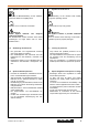
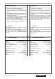
Einstellknopf
Adjusting knob
Manometer
Pressure gauge
Filtereinsatz
Filter element
Behälter
Tank
Manueller Ablass
Manual outflow
Bild / Picture 3: Wartungseinheit / Maintenance unit