
Brochure/Catalogue


for EMR
for SSR
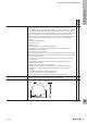
Derating / derating curve Flowing current causes heat, which increases with increasing current intensity.
Electric components have an upper limit temperature which limits their
functionality. Because the temperature inuence on the components is made up
of the ambient temperature and the heat generated by the current, the current
must be reduced as the ambient temperature increases so as not to exceed the
upper limit temperature. The relationship between the prevailing ambient
temperature and the resulting maximum current is shown in the derating curve.
Unless otherwise specied, the derating curves are given for the following
conditions:
• Max. rated control voltage
• 100% duty cycle
• Resistive load
• Closely packed with several identical products
• Horizontally and vertically oriented terminal rail (in an upright cabinet)
• No ventilation in the cabinet
• No shading by cable conduits
The heating of the product can be increased by the following parameters, which
can lead to heating above the limit temperature and therefore to damage or even
destruction of the product:
• Shading, e.g. by cable conduits tted too narrowly, which can lead to heat
accumulation
• High switching frequencies, especially when switching high currents or
inductive loads (arcing)
• Warmth from other devices mounted nearby
The heating of the product can be reduced by the following parameters:
• Reduction of shading by increasing the distances to cable conduits, for
example
• Increasing the ventilation in the control cabinet
• Increasing the distance to adjacent products
• Avoiding the effects of heat from other devices mounted nearby
x x
Dielectric strength Voltage (RMS value for AC voltage, 50 Hz, 1 min) which can be applied between
mutually insulated relay components during the voltage test.
x x
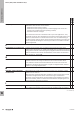
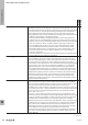
Dimensions Dimensions in millimetres.
'HSWK
+HLJKW
:LGWK
x x
EMR = Electromechanical relay
SSR = Solid-state relay
Glossary: Relay modules and Solid-state relays
W
Technical appendix/Glossary
W.212737920000