
Brochure/Catalogue

for EMR
for SSR
E
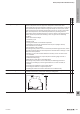
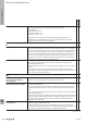
Electrical endurance,
Electrical endurance curve,
contact endurance
Number of switching cycles of a relay with electrical contact load under full
operational capability. Unless otherwise stated, the contact data and electrical
lifespan curves are valid under the following conditions:
• Measured at the NO contact
• Resistive AC load
• AC mains frequency 50 Hz
• Duty cycle 50%
• Switching frequency 0.1 Hz
• Rated control voltage (coil)
• Ambient temperature 23°C
• Individual assembly
The electrical lifespan is specied according to the criteria for ‚useful life‘, severity
level B according to IEC 61810-2. The data does not cover any use beyond
the specied electrical lifespan; it is the responsibility of the user to avoid such
situations. Experience has shown that the electrical lifespan remains relatively
constant with an AC load up to a power factor (cos φ) of 0.8.
However, each load places different demands on the switching contact and other
environmental factors also inuence the service life of the switching contact, e.g.
the type of load, the switching voltage at the contact, the switching current of
the load, any inrush currents, the ambient temperature, the mounting position,
the switching frequency and many more.
Therefore, the real service life could be either above or below the specied value.
For loads other than those specied in the service life data, it is recommended
that user advice be followed; alternatively, recommendations can be found in the
selection table in Chapter ....
For critical applications it is recommended that the service life values be
determined independently by the user.
Please note: The curve for the electrical lifespan species the typical service life
as the “Mean Cycles to Failure“ (MCTF) and is based on the Weibull distribution.
No guaranteed minimum values can be interpreted from this statistical data.
The electrical lifespan must not be compared with the mechanical lifespan when
switching larger or inductive loads, as the mechanical lifespan is measured
without contact load and the failure criteria are different. The difference between
the mechanical and electrical lifespans becomes greater as the switching current
increases. For more information on the mechanical lifespan, see item entitled
“Mechanical lifespan“.
x
EMR = Electromechanical relay
SSR = Solid-state relay
Glossary: Relay modules and Solid-state relays
W
Technical appendix/Glossary
W.232737920000