
Brochure/Catalogue

for EMR
for SSR
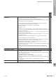
Protective circuit on the
control side (solid-state relay)
or
protective circuit
(electromechanical relay)
at the input
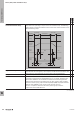
The protective suppressor circuit at the input can either be plugged into the
socket by a plug-in module or it can be integrated into the electromechanical
relay or the solid-state relay. The various protective suppressor circuits and their
function are explained below:
Free-wheeling diode:
Protects only the control electronics from the inductive cut-off voltages of the
relay coil of an electromechanical relay with DC coil.
Attention: If no additional reverse polarity protection has been previously
installed, a short circuit can be caused by reverse polarity.
Varistor:
Protects the input of an electromechanical relay or solid-state relay from surge
voltages.
In electromechanical relays, it also protects the control electronics from the
inductive cut-off voltages of the relay coil.
Rectier:
Enables AC and DC voltages to be connected as a protective suppressor circuit in
the input without prescribing a polarity direction.
In electromechanical relays, it also protects the control electronics from the
inductive cut-off voltages of the coil.
RC element:
Protects the control electronics from the inductive cut-off voltages of the relay
coil of an electromechanical relay with AC coil.
Coupled voltages in long control lines at the input may mean that an
electromechanical relay or solid-state relay no longer switches off reliably.
An RC element allows for the reduction of the coupled voltages, which can cause
the electromechanical relay or solid-state relay to drop out.
x x
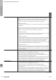
Protective circuit, load side
(solid-state relay)
Protective suppressor circuit integrated in the output of the solid-state relay.
The protective suppressor circuit at the output of a solid-state relay protects
the output against surge voltages such as those that occur when switching off
inductive loads.
Due to the very compact design of pluggable solid-state relays such as those
used in the TERMSERIES as well as the limited heat dissipation, the protective
suppressor circuit of these solid-state relays often only offers protection against
small surge voltages, e.g. from very light inductive loads.
It is therefore highly recommended to have an additional external protective
suppressor circuit parallel to the load when switching inductive loads with
these pluggable solid-state relays. Otherwise, the semiconductor output may be
destroyed.
When switching inductive loads with switching frequencies faster than 0.5 Hz, an
external protective suppressor circuit must be connected in parallel with the load.
If this is not possible, solid-state relays specially designed for switching inductive
loads must be selected.
x
EMR = Electromechanical relay
SSR = Solid-state relay
Glossary: Relay modules and Solid-state relays
W
Technical appendix/Glossary
W.32 2737920000