
Brochure/Catalogue


Additional information on the selection tables
Simple formulas for calculating individual values
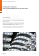
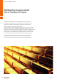
Calculating the service life of the relay contacts
for different switching currents
In the previous tables we gave you the maximum
recommended currents at various loads for a
service life of approx. 100,000 switching cycles.
If you switch lower currents, the service life of the
relay contacts will be extended. With the following
formulas you can approximately calculate how
the service life of the relay contacts will change.
Example: A 24 V DC solenoid valve with 200 mA current
consumption should be switched with a 6.4 mm wide
TERMSERIESRSS1CO relay. A solenoid valve corresponds
to a DC13 load. According to the table, a switching
current of max. 1 A is specified for the relay at this load.
To calculate the expected service life, proceed as follows:
x =
I
App
I
Table
=
200 mA
1 A
=
5
n
new
= 100.000 • x = 100.000 • 5 = 500.000 switching cycles
The expected service life when switching a 200 mA solenoid
valve should be approx. 500,000 switching cycles.
Calculating the switching currents for voltages
that deviate from the values in the table
AC switching voltage:
With AC loads, the switching current has the greatest
influence on the service life. Therefore, the switching
currents from the table can also be used for switching
voltages up to 100 V AC. For values below 100 V AC,
the service life increases at the same switching current:
• at 24 V AC four times the service life
• at 60 V AC twice the service life
Example: If the table shows a switching current of 2 A for
a 250 V AC AC15 load, then these 2 A are also applicable
for 120 V AC. At 24 V AC switching voltage, the expected
service life increases four times to 400,000 switching cycles.
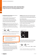
DC switching voltage:
When switching DC loads, the switched voltage has a large
influence on the maximum switching current of the relay
contact. This can also be seen from the DC load breaking
curve given in the data sheet. The following formulas can
be used to roughly determine the maximal switching
current for other DC switching voltages:
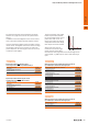
Example: A TERMSERIESRCL1CO relay with a DC13
load and a switching voltage of 110 V DC. According to
the table a maximum of 2 A at 24 V DC applies to a DC-13
load for a service life of 100,000 switching cycles.
The curve shows a maximum switching current of approx.
0.45 A with resistive load. This must now be set in relation
to the rated current of the relay (16 A) from the data
sheet and the value for a DC13 load from the table.
x =
I
Nom
I
Table
=
16 A
2 A
=
0.125
I
DC
= I
Load curve
• x = 0.45 A •
0.125 = 0.056 A = 56 mA
To achieve 100,000 switching cycles, a DC13 load of 56
mA can be switched with a switching voltage of 110 V DC.
I
App
= Switching current in the application
I
DC
= DC Switching current at the DC switching voltage in the application
I
Load curve
= DC Switching current from the load limit curve of the data sheet
I
Nom
= Continuous current from relay data sheet
I
Table
= Switching current from the selection table for the respective load
n
new
= Service life at switching current in the application
x = Reduction factor of the switching current
Switching voltage [V DC]
Switching current [A]
1 contact
300
200
100
50
40
30
20
10
0.1 0.2 0.5 12 51020
DC load breaking capacity
Resistive load
A.8 2737920000
Selection guide
A
Simple formulas for calculating individual values