
User Documentation


Installation
2053260000/05/2015
137
• What type of bre has been laid (singlemode bre, multimode bre, hard
cladded silica, plastic optical bre)?
• What plug type is used?
• Roughly how long a section has been laid?
Table 3.2 shows the types of glass bre used by PROFINET and the permissible
limit values for the PROFINET end-to-end link attenuation depending on the
operating wavelength.
Origin Singlemode
glass bre
Multimode
glass bre
PCF POF
Typicalwavelength 1,310 nm 1,300 nm 650 nm 650 nm
Maximumpermitted
end-to-endlink
attenuation
10.3 dB 62.5/125μm:11.3dB
…
50/125μm:6.3dB
4.75 dB 12.5 dB
Table3.2:MaximumpermittedPROFINETFOend-to-endlinkattenuation
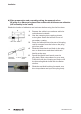
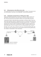
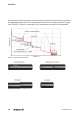
There are two parts to the measurement. Firstly, the measurement setup has to
be calibrated. To do this, the reference bres are connected with one another as
shown in Figure 3.5 and a reference measurement is taken. The receiver saves
the light power received in this setup as a reference value for a section without
attenuation.
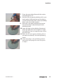
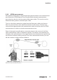
The two reference bres are then isolated and the section to be tested added. The
actual section measurement then follows and the tester measures the light power
received by the receiver and compares this with the saved reference value. The
difference between the two measurements is displayed as the attenuation for the
section added.
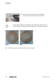
Defects on the plugs of the reference bres to the test specimen inuence the result.
Only selected assemblies, approximating to an ideal plug, may therefore be used.