
User Documentation


IE-CS(T)-2TX-xRS232/485 Getting Started
2-3
Wiring Requirements
ATTENTION
Safety First!
Be sure to disconnect the power cord before installing and/or wiring your IE-CS(T)-2TX-xRS232/485.
Wiring Caution!
Calculate the maximum possible current in each power wire and common wire. Observe all electrical codes
dictating the maximum current allowable for each wire size.
If the current goes above the maximum ratings, the wiring could overheat, causing serious damage to your
equipment.
Temperature Caution!
Please take care when handling the IE-CS(T)-2TX-xRS232/485. When plugged in, the
IE-CS(T)-2TX-xRS232/485’s internal components generate heat, and consequently the casing may feel hot to
the touch. When installed with other components, make sure that there is at least 2 cm clearance on all sides
of the IE-CS(T)-2TX-xRS232/485 in order to allow proper heat dissipation.
You should heed the following:
• Use separate paths to route wiring for power and devices. If power wiring and device wiring paths must
cross, make sure the wires are perpendicular at the intersection point.
NOTE: Do not run signal or communication wiring and power wiring in the same wire conduit. To
avoid interference, wires with different signal characteristics should be routed separately.
• You can use the type of signal transmitted through a wire to determine which wires should be kept separate.
The rule of thumb is that wiring that shares similar electrical characteristics can be bundled together.
• Keep input wiring and output wiring separate.
• Where necessary, it is strongly advised that you label wiring to all devices in the system.
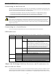
Connecting the Power
Connect the 12-48 VDC power line with the IE-CS(T)-2TX-xRS232/485’s terminal block. If the power is
properly supplied, the “Ready” LED will show a solid red color until the system is ready, at which time the
“Ready” LED will change to a green color.
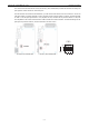
Grounding the IE-CS(T)-2TX-xRS232/485
Grounding and wire routing helps limit the effects of noise caused by electromagnetic interference (EMI). Run
the ground connection from the ground screw to the grounding surface prior to connecting devices.
WARNING
This product is intended to be mounted to a well-grounded mounting surface such as a metal panel.
SG:
T
he Shielded Ground (sometimes called Protected Ground) contact
is the left most contact of the 8 contact power terminal block
connector when viewed from the angle shown here. Connect the SG
wire to an appropriate grounded metal surface.