GB IE-CT Weidmüller Interface GmbH & Co. KG Postfach 3030 32720 Detmold Telefon +49 5231 14-0 Telefax +49 5231 14-2083 info@weidmueller.com www.weidmueller.
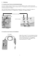
IE-CT IE-CT Grundgerät IE-CT Mainframe IE-CT Testbox IE-CT Test Box K F B E G C D H I J A GB A = B = C = D E F G H I J K = = = = = = = = Anschlussleitung 7-Segmentanzeige neun Einstellschalter (unter dem Schutzgummi) Ein-/Aus- und Starttaste RJ45-Anschlussbuchse neun rote LEDs grüne LED Step-Taste zur Fehlerabfrage Fehlerbeschreibung Anschlussleitung RJ45-Anschlussbuchse A = B = C = D E F G H I J K 2 = = = = = = = = attachment cord numeric display nine Selection Switches (under protective co
Inhaltsverzeichnis 1. Einleitung . . . . . . . . . . . . . . . . . . . . . . . . . . . . . . . . . . . . . . . . . . . . . . . . . . . . . . . . . . . . . . . . 2 1.1 Lieferumfang . . . . . . . . . . . . . . . . . . . . . . . . . . . . . . . . . . . . . . . . . . . . . . . . . . . . . . . . . . 2 2. Sicherheitshinweise . . . . . . . . . . . . . . . . . . . . . . . . . . . . . . . . . . . . . . . . . . . . . . . . . . . . . . . . 2 3. Leistungsmerkmale . . . . . . . . . . . . . . . . . . . . . . .
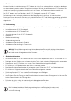
1. Einleitung Mit dem Kauf des Installationstesters IE-CT haben Sie sich für ein unkompliziertes, einfach zu bedienendes aber dennoch professionelles Testgerät entschieden. Mit dem Installationstester IE-CT können Sie schnell und zuverlässig Installationsanschlüsse in der Daten- und Telekommunikationstechnik auf Installationsfehler überprüfen. Der IE-CT besteht aus zwei Geräten, dem IE-CT Grundgerät und der IE-CT Testbox.
3. Leistungsmerkmale • Erkennung und Anzeige der häufigsten Installationsfehler: Kurzschluss, Aderunterbrechung, Adernvertauschung, Leitungsvertauschung, Aderverwechslung (split pair). • Selbsttestfunktion und Wackelkontakttest. • Fehleranzeige für jede Ader durch acht rote Ader-LEDs und eine Schirm-LED (F). • Anzeige durch eine grüne LED (G), wenn kein Fehler festgestellt wurde. • Ein, Aus und Start des Testvorganges durch eine Taste (D).
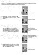
4. Inbetriebnahme Bevor Sie den Installationstester IE-CT in Betrieb nehmen, müssen Sie zunächst die mitgelieferte 9-V-Blockbatterie einlegen. 1. Lösen Sie die beiden Schrauben am Bodenteil des Gehäuses und nehmen Sie das Bodenteil ab. Nun erkennen Sie im unteren Bereich des Gehäuseoberteils das Batteriefach, in dem sich der Anschlussclip für die Batterie befindet. 2. Drücken Sie den Batterieclip auf die Batterie und legen Sie die Batterie in das Batteriefach.
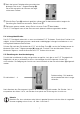
5. Bedienung 5.1 Anschluss zum Testen von Installationsleitungen Um eine installierte Leitung mit dem IE-CT auf Installationsfehler zu testen, stecken Sie das eine Ende der Installationsleitung in die RJ45-Buchse des IE-CT Grundgeräts und das andere Ende in die RJ45-Buchse der IE-CT Testbox. Wenn eine gleichzeitige Leitungsidentifikation durchgeführt werden soll, stecken Sie in jeden zu testenden Anschluss eine IE-CT Testbox (max. 9 Testboxen, als Zubehör erhältlich).
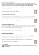
5.3 Einschalten und Testen Sind das IE-CT Grundgerät und die IE-CT Testbox angeschlossen, kann der Installationstest und die Leitungsidentifikation nach folgendem Schema durchgeführt werden. % Einschalten des IE-CT Grundgerätes durch Drücken der Starttaste (D). Starttaste drücken # Während des Tests blinkt die grüne LED (G). Wenn die grüne LED aufhört zu blinken, ist der Test beendet.
& Nach der letzten Fehlerdarstellung erscheint eine blinkende Ziffer in der 7-Segmentanzeige (B). Diese Ziffer entspricht der Nummer der angeschlossenen Testbox. ' Wird die Step-Taste (H) nochmals gedrückt während die Testboxnummer blinkt, beginnt die Darstellung der Fehlerliste von neuem. Siehe Punkt !. ( Soll erneut getestet werden, fahren Sie fort wie unter Punkt % beschrieben. Das IE-CT Grundgerät kann mit der Starttaste auch jederzeit wieder ausgeschaltet werden. 5.
5.6 Fremdspannung (Fehlercode 1) Der IE-CT ist fremdspannungsfest (bis 100 V kurzzeitig) und kann Fremdspannungen am Anschluss nach Polarität und Aufschaltung auf der Ader anzeigen. Der positive Pol der Fremdspannung wird durch Dauerleuchten, der negative Pol durch Blinken der entsprechenden Ader-LED (F) angezeigt. Wird an dem zu testenden Anschluss eine Fremdspannung festgestellt, ist der Testvorgang beendet.
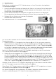
5.10 Vertauschung (Fehlercode 5) Erkennt der IE-CT in der Installation oder im Kabel vertauschte Adern, leuchten die Ader-LEDs (F) der dazugehörigen Adern immer paarweise. Die Ader-LED für die Anschlussklemme am nahen Ende der Installationsleitung leuchtet dauernd und die Ader-LED für die Anschlussklemme am fernen Ende blinkt. Beispiel: IE-CT Grundgerät Anschluss nahes Ende Installationsleitung Anschluss fernes Ende IE-CT Testbox In unserem Beispiel werden zwei Fehler erkannt: 1.
5.11 Schalterstellung (Fehlercode 6) Sind die Einstellschalter (C) des IE-CT Grundgerätes falsch eingestellt, das heißt, es sind mehr Adern am Anschluss aufgelegt als mit den Einstellschaltern (C) ausgewählt, wird dies vom IE-CT Grundgerät erkannt. Wurden Einstellschalter für angeschlossene Adern ausgeschaltet, leuchten die entsprechenden roten Ader-LEDs (F). Der Fehlercode für falsche Schalterstellung ist die Ziffer 6. 5.
6.
7. Wackelkontakt Vermuten Sie bei einem Anschlussmittel, wie z.B. Anschlussdose, Anschlusskabel oder Adapter, einen Wackelkontakt, kann dieser Fehler mit dem IE-CT festgestellt werden. Solch ein Wackelkontaktfehler kann nur gefunden werden, wenn das verwendete Testgerät ständig die Durchgängigkeit der Anschlüsse prüft, während das Anschlussmittel bewegt wird. Für diesen Testvorgang hat der IE-CT eine separate Betriebsart.
9. Technische Daten Gewicht IE-CT Grundgerät ca. 185 g (mit Batterie) IE-CT Testbox ca. 31 g Abmessungen IE-CT Grundgerät (B x H x T) 70 mm x 140 mm x 36 mm IE-CT Testbox (B x H x T) 30 mm x 68 mm x 23 mm Max. Leitungslänge ca. 1000 m Fremdspannungsfestigkeit 80 V Daueranschluss, 100 V kurzzeitig (bis 5 Min.) Prüfspannung <5V Automatische Geräteabschaltung nach 30 Sekunden Spannungsversorgung 9-V-Blockbatterie Anschlussleitungen 9-adrig Anschlusssystem RJ45 10.
14
Contents 1. GB Introduction . . . . . . . . . . . . . . . . . . . . . . . . . . . . . . . . . . . . . . . . . . . . . . . . . . . . . . . . . . . . . . 16 1.1 Contents of Packing Unit . . . . . . . . . . . . . . . . . . . . . . . . . . . . . . . . . . . . . . . . . . . . . . . . 16 2. Safety Instructions . . . . . . . . . . . . . . . . . . . . . . . . . . . . . . . . . . . . . . . . . . . . . . . . . . . . . . . . . 16 3. Features . . . . . . . . . . . . . . . . . . . . . . . . . . . . . . . . . . .
1. Introduction By purchasing the installation tester IE-CT you have decided to opt for an easy and professional piece of test equipment that is easy to use. This tester is designed for quick and reliable recognition of installation faults in data and telecommunication wiring. IE-CT includes two devices – IE-CT Mainframe and IE-CT Test Box. The number of conductors of the cable installation and the pin assignment can be set individually.
3. Features • Recognition and display of the most frequent installation errors: short circuit, line/wire interrupt, line/wire mistakes, split pair • Self test function and intermittent contact test • Error display for each conductor by eight red conductor LED’s and one red LED for the shield (F). • Display of no error by green LED (G). • One key for ON, OFF and start of the test operation (D). • Separate Step Key (H) to display list of multiple errors.
4. Startup Procedure Before operation put in the 9 V block battery first. 1. Unscrew the two screws on the bottom of the unit and take this part away. You will find the battery case with the connector clip for the battery. 2. Press the clip on to the battery and put the battery into the battery case. Should the battery be contacted with the wrong polarity the IE-CT will not be damaged. 3. Close the lid and fasten the screws.
5. Operation 5.1 Connection to Test Installation Lines To test an installed line plug one end of the installation line to the IE-CT Mainframe and the other end to the IE-CT Test Box. To do a simultaneous line identification plug one IE-CT Test Box to each termination to be tested (max. 9 Test Boxes, available as accessories). Installation Lines Patch Panel Wall Outlets IE-CT Test Boxes IE-CT Mainframe 5.
5.3 Switch on and Test Terminate IE-CT Mainframe and IE-CT Test Box, then start the installation test and line identification as shown below. % Press the Start Key (D) to turn on the IE-CT Mainframe. press Start Key # During the test run, the green LED (G) flashes. The test is finished when the green LED stops flashing. The green LED flashes $ The green LED (G) lights without interruption if no errors were detected, the installation is OK.
& After the last error is displayed a flashing digit is shown in the numeric display (B). This digit stands for the number of the connected Test Box. ' If you press the Step Key (H) again as long as the Test Box number is flashing, the error list is shown a second time, see item !. ( For repeated testing continue as described under item %. The IE-CT Mainframe can be turned off at any time by pressing the Start Key. 5.
5.6 Extraneous Voltage (Error Code 1) The IE-CT resists to extraneous voltages (short time up to 100 V). If extraneous voltages should appear in the installation the IE-CT can show their polarity and the respective conductor. The positive pole of an extraneous voltage is displayed by continuous lighting, and the negative pole is displayed by flashing of the respective conductor LED (F). If an extraneous voltage is detected in an installation the test run is finished.
5.10 Wrong Wiring (Error Code 5) If the IE-CT detects wrong termintated conductors in an installation or cable the conductor LED (F) for the respective conductors always light in pairs. The conductor LED for the terminal pole at the near end of the installation line lights continuously, the conductor LED for the terminal pole at the far end is flashing. IE-CT Mainframe near end of Installation line Installation line far end of Installation line IE-CT Test Box In our example two errors are detected: 1.
5.11 Switch Setting (Error Code 6) If the Selection Switches are not correctly set (C) on the IE-CT Mainframe, i. e. if the installation has more conductors than selected, the IE-CT Mainframe will recognize this. If connected conductors have been separated with the Selection Switches, the respective red conductor LED (F) will light. The error code for wrong switch setting is digit 6. 5.12 Battery (Error Code 7) If the battery power is too low the IE-CT Mainframe will show this in the numeric display (B).
6.
7. Intermittent contact If you are operating a termination unit such as wall outlet, cable or adaptor where you supect an intermittent contact, IE-CT will help you to detect this error. Intermittent contact detection requires constant checking of the connections when the termination unit is moving. IE-CT offers an additional operation mode. Terminate the unit to be tested between the IE-CT Mainframe and one of the Test Boxes (see chapter 6.2) to check for intermittent contact.
9. Technical Data Weight IE-CT Mainframe approx. 185 g (with battery) IE-CT Test Box approx. 31 g Dimensions IE-CT Mainframe (B x H x T) 70 mm x 140 mm x 36 mm IE-CT Test Box (B x H x T) 30 mm x 68 mm x 23 mm Maximum line length approx. 1000 m Electric strength 80 V continuous connection 100 V short time (up to 5 min.) Automatic shut down after 30 s Test voltage <5V Power supply 9 V block battery Attachment cords 9 conductors Termination system RJ45 10.
28