
User Documentation


2053260000/05/2015136
Installation
3.9 Measurement on the bre-optic cable
This chapter describes how to assess your bre-optic cabling. The measurement
recommendations are based on the PROFINET commissioning guideline.
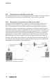
3.9.1 Attenuation measurement for bre-optic cables
The most important parameter to monitor on a bre-optic cable section is its
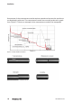
attenuation. The insertion loss process (Figure 3.5) is the easiest way to do
this. The measurement process detects losses in the optical bres and their
connections. Light is transmitted by a transmitter via reference bre 2 into one
end of the bre-optic cabling. A calibrated receiver is connected to the other end
of the bre-optic cabling being tested via another reference bre 1. The receiver
measures the amount of light received and evaluates any losses incurred. The
attenuation or insertion loss is usually stated in dB. The reference bre 2 at the
transmitter end is wound in several coils on a winding spindle with a dened
diameter. The “mode mixer” produced in this way correctly distributes light into
the reference bre and prevents the measurement result from being affected by
the radiation characteristics of the transmitter.
Figure 3.5: Principle of the attenuation measurement