
User Documentation

5
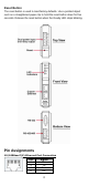
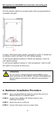
DIP switches for RS422/485 line termination and setting pull
high/low resistors
The DIP switches (SW1) are located inside of the housing behind the
screwable side-gate.
To add a 120 Ω termination resistor, set switch 3 to ON. To disable the
termination resistor set switch 3 to OFF (default setting).
To set the pull high/low resistors to 150 KΩ, set switches 1 and 2 to
OFF (default setting).
To set the pull high/low resistors to 1 KΩ, set switches 1 and 2 to ON.
DIP switch 4 is reserved for future use.
ATTENTION
Do not use the 1 KΩ pull high/low setting ON the device
when using the RS-232 interface. Doing so will degrade the
RS-232 signals and reduce the effective communication
distance.
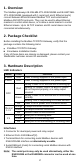
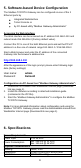
4. Hardware Installation Procedure
STEP 1:
Use a standard Ethernet cable to connect the unit to an
Ethernet device or a network switch.
STEP 2:
Connect your Modbus RTU/ASCII device to the
Gateway's serial port.
STEP 3:
Mount the unit on a DIN-rail.
STEP 4:
Connect the power source to power input.