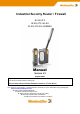
Industrial Security Router / Firewall IE-SR-4TX IE-SR-4TX-4G-EU IE-SR-4TX-4G-USEMEA Manual Version 1.2 August 2020 Important notes: This document will be updated continuously. This version refers to Router firmware version 1.0.7 and above. This document, new firmware or additional product information can be downloaded using following link: https://catalog.weidmueller.
Industrial Security Router / Firewall Manual The software described in this manual is furnished under a license agreement and may be used only in accordance with the terms of that agreement. Copyright Notice Copyright 2020 Weidmüller Interface GmbH & Co. KG All rights reserved. Reproduction without permission is prohibited. Disclaimer Information in this document is subject to change without notice and does not represent a commitment on the part of Weidmüller.
Table of Contents INDUSTRIAL SECURITY ROUTER / FIREWALL ............................................................................................................... 1 1. INTRODUCTION................................................................................................................................................... 5 1.1 Proper and intended usage............................................................................................................................. 5 1.
Network → IP Routing (Tab State) .................................................................................................................................... 42 Network → HTTP proxy.................................................................................................................................................... 42 Network → Forwarding....................................................................................................................................................
1. Introduction 1.1 Proper and intended usage The Router is intended for use in industrial (IP20) environments. It is equipped with Ethernet interface ports and is used solely for connecting components within a network. By connecting network components, the Router enables network nodes to exchange data between the LAN and WAN port. By connecting an external DSL modem (via PPPoE) at WAN the Router can provide a direct connection to the Internet.
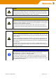
Caution - This device is designed only for an operating voltage range from 19,2 to 28,8 V DC. Do not use a higher voltage; this could destroy the Router and other devices. - The Security Router does not have an on/off switch. The operating voltage must be switched on by the facility in which the device is integrated.
1.4 Mounting the device Caution - This device is designed only for an operating voltage range from 19,2 to 28,8 V DC. Do not use a higher voltage; this could destroy the Router and other devices. - Connecting plugs should never be connected or disconnected from electrical devices if they are carrying a live load. Be sure to first disconnect all poles of the plug. Remember to disconnect all plugs from the Router before it is installed or removed.
1.5 Technical data Operation mode • • IPv4-Routing between the interfaces (LAN ports / WAN port / optional 4G modem). LAN-Ports behave as unmanaged switch. Static or dynamic routing according to RIPv2 or OSPF protocol.
Configuration Management • • • • • • • Configuration with web interface (HTTP/HTTPS) Web interface selectable in English or German language Configuration support through wizard Configuration support through detailed help information (tooltip) Configurable Multi-user access with definable rights Support for SNMP v1/v3/v3 Event log / syslog Other features Modbus/TCP (Slave mode) The integrated Modbus/TCP Slave provides control functions sent by a Modbus/TCP master.
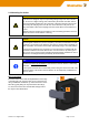
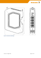
Figure 1: Dimensional drawings Version 1.
Environmental conditions Operating Temperature • -30°C to +70°C Storage Temperature • -40°C to + 85°C Ambient Humidity • 5 to 90% non-condensing DSL and 4G/LTE DSL • DSL Internet access by connecting to an external DSL modem via LAN or WAN port • Free configuration of the PPPoE login DynDNS • Support for automatic DNS registration (DynDNS.
Antenna gain and frequencies: • 1 dBi @ 698-960 MHz • 2 dBi @ 1710-1990 MHz • 2 dBi @ 2300-2400 MHz • 3 dBi @ 2500-2700 MHz • Polarisation: vertical Antennas* * Only 4G models Approvals Safety EMC Shock Vibration Warranty Period • • • • • • cULus (UL 61010) FCC Part 15 Class A, EN61000-6-2 Immunity for industrial environments EN61000-6-4 Emission Standard for industrial environments DIN EN 60068-2-27 DIN EN 60068-2-6 3 years Order Information 2-Port LAN/WAN Router with VPN features 2-Port LAN / WAN Ro
2. Hardware related functional descriptions 2.
2.
2.
3. Initial start-up / Getting Started 3.1 Configuration of the Router by using an Internet browser Note The configuration of the device can be done either via LAN or WAN RJ45 ports. Connect the unit to a 24V DC (4-pin plug) power source. The corresponding plug is included. During the initial boot phase, the PWR LED is flashing. The Router is ready when the PWR LED is lit constantly (after about 30 seconds). Connect the Router to the Ethernet interface of a configuration PC using a RJ45 network cable.
2. Now the login prompt of the Router should appear for input User name and Password. Default values (factory settings) for Login: User name: admin Password: Detmold Confirm your input by pressing the Log in button. Now the Router homepage is displayed. This page corresponds to the menu item "Diagnostics → System State." On this page the most important configuration and status information are summarized.
3.3 Default factory settings of the Router: Note Some fields are linked with a hyperlink to jump directly into the corresponding menu item. Language English Operation Mode IP Router IP address LAN Port(s) 192.168.1.110 (static value) Subnet Mask 255.255.255.0 NAT (Masquerading) on LAN Port Not activated IP address WAN Port DHCP client Subnet Mask 255.255.255.
3.5 Using the Weidmüller Router-Search-Utility The software tool Weidmüller Router-Search-Utility can be used to find Weidmüller Routers and detect their IP addresses within a switched network. This software is very helpful if you don’t know the current IP address of a Router. This can e.g. happen in cases that you have forgotten the current IP configuration or you have lost the Router access in case of configuring an unintended IP address.
3.
4. Web Configuration 4.1 Section Diagnostics 4.1.1 Diagnostics → System State Menu Diagnostics → System State Function Startup screen of the web interface after login. Displays current configuration and status data. System name Name of the device, default “-” Device type Article Name Serial No.
4.1.2 Diagnostics → Event Log (Tab State) Menu Diagnostics → Event Log →Tab State Function Display events and error messages that have occurred in chronological order. Message syntax: : Message 4.1.3 Diagnostics → Event Log (Tab Configuration) Menu Diagnostics → Event Log →Tab Configuration Function Event and error messages can be sent to a syslog server (PC on the network) or sent as emails.
4.1.4 Diagnostics → WAN Menu Diagnostics → WAN Function Displays the current status of the WAN ports Diagnose the WAN-port. 4.1.5 Diagnostics → LAN Menu Diagnostics → LAN Function Displays the current status of the LAN ports. Diagnose the LAN-port. Version 1.
4.1.6 Diagnostics → WWAN Menu Diagnostics → 4G Function Displays the current status of the 4G mobile connection. Menu available for cellular models only. 4.1.7 Diagnostics → Ping test Menu Diagnostics → Ping test Function Allows sending of ICMP packets (ping) to test network connections between the Router and other Ethernet devices. To test internet connection, to use u-link Remote Access Service for example, try to ping a well-known internet IP address like 8.8.8.8, the DNS server of google.
Example of result of a ping test: 4.1.8 Diagnostics → Remote capture Menu Diagnostics → Remote capture Function By using the "remote capture" function data packets on both the LAN and the WAN port of the Router can be recorded for diagnostic purposes. The receiver of the diagnostic data is a PC/Server which must have installed the tool "Wireshark" listening on Port 2002. How to use please refer to application note in Appendix A.
4.2 Section Configuration 4.2.1 Configuration → Config Wizard Menu Configuration → Config Wizard Function The Config Wizard is a tool which helps setting up the major functions of the router. It will be displayed automatically at the initial configuration but may be used later for configuration change as well. Language Setting the language of the Router Web interface Load settings Load a configuration file created before. Password Change the default password to a new one.
WAN configuration Configure the WAN-Interface of the router. This can be done via DHCP client (factory default), static IP and Mobile Broadband. The status LED’s will turn green, if settings work. For more information on the settings please refer to the respective chapter. Date & Time Setting the router system time via a time server or manually. When choosing manually please consider that the router will loose time settings after 15 minutes without power. Version 1.
Proxy If you need to pass a Proxy you can set a system wide Proxy here. The router will test it’s https connection to the u-link server. The status LED’s will turn green, if settings work. u-link u-link With the u-link remote access service you can easy and without ITknow-how do a secure remote access on the networks attached to this router. Register on www.u-link.weidmueller.com and create a router-object to get a Registration code. The status LED’s will turn green, if settings work. Version 1.
Overview u-link Summarizes your settings. Download Settings to store the configuration or to load this configuration into another router. Save settings to activate the settings on this router. The status LED’s will turn green, if settings work. Version 1.
4.2.1 Configuration → IP Configuration IP Configuration → Operational mode “IP Router” Screenshot shows factory default operation mode ‘IP Router’. At factory default all 2-Port Routers do have configured static IP 192.168.2.110 at WAN port. At factory default all 6-Port Routers do have configured the DHCP mode for getting an IP address. At factory default all Router variants do have configured static IP 192.168.1.110 at LAN port. Section 4G is only available for models with 4G interface.
Dialmode Disabled: Do not use 4G modem. Manual: Dialing can be triggered manually from 4G status page. Permanent: The 4G link will be established automatically on system boot. Fallback: The 4G link will go online if the monitoring on the given interface “Fallback for interface” fails. The system will actively monitor the given IP addresses on the given interface. After a failure of at least 30 seconds the 4G link will be established. PIN The Pin of your SIM-Card.
4.2.3 Configuration → Packet filter (Firewall) Packet filter → Tab Layer 3 Menu Configuration → Packet filter → Tab „Layer 3” Function This is the window for the manual configuration of firewall filter rules based on Layer 3 (IP layer). The screenshot shows the firewall settings as delivered with the default rule "Allow_L3*". This rule says that any IP protocol (*) and any traffic regardless the direction (source and destination=*) is allowed.
Packet filter → Tab Status Menu Configuration → Packet filter → Tab „Status“ Function Overview of transmit and receive activities of the physical and virtual interfaces. 4.2.5 Configuration → General settings General settings → System data Menu Configuration → General settings → System data Function Configuring application-related data of the Router (free text). System name Name of the router (by default the Router model name). Can be edited if checkbox ‘Serial no. as system name’ is disabled.
Menu Configuration → General settings → Date & time Function Setting of date, time and time zone. Alternatively, the date/time setting can be configured using the "Network Time Protocol" NTP and accessing an external NTP server. When NTP time server relay is activated, the device will be act as a NTP time server for other services. Note 1. The Router has no battery-buffered, but a capacity-buffered system clock. 2. General behavior of date/time settings: 3.
General settings → User Interface Configuration → General settings → User interface Menu Function Language Setting the language (German or English) of the Web interface. Save and apply: • Apply immediately and do not save Changes will be immediately activated but not saved. The new activated changes have to be saved explicitly in menu System → Save. • Save only and do not apply Using this mode all changes will only be saved but not activated. The changes come into effect after a restart.
General settings → SCEP (Tab Configuration) Menu Configuration → General settings → SCEP Function Configuration of the Router for online access to certificates which are stored on a centralized online certificate server (SCEP Simple Certification Enrollment Protocol). When setting up certificate-based VPN connections, the necessary certificates can be obtained directly from a SCEP server. Server URL e.g. http://192.168.1.1/certsrv/mscep.
4.2.6 Configuration → Access Control Access Control → User accounts Menu Configuration → Access control → User accounts Function Create and delete other user accounts Note: The Administrator account always has full access. It cannot be deleted. Access Control → Permissions Menu Configuration → Access control → Permissions Function Detailed assignment of individual rights for each created user account. Note: The Administrator account always has full access. It cannot be changed or deleted.
Access Control → Web access Menu Configuration → Access control → Web access Function Select the possible access modes of the web interface (via http and / or https) for the different interfaces. For cellular models additional checkboxes named „WWAN“ will be displayed to control access to the Web interface via 4G connection. In extended routing mode or if VPN is used, all interfaces will be displayed if they represent different subnets. 4.2.
If the interface for accessing the Internet (e.g. WAN port) is configured statically then you must configure at least one accessible DNS server for resolving DNS names (e.g Google’s name server with IP 8.8.8.8). st nd 1 , 2 , 3rd DNS server If the Interface for Internet access is set to DHCP then typically the DNS server will be retrieved from DHCP server. In this case you do not need to enter the IP address of a DNS server.
Network → IP Routing (Tab Configuration) Menu Configuration → Network → IP Routing → Tab „Configuration“ Function Registration of static IP routes and activating/deactivating of dynamic routing. For dynamic routing, both can be selected the RIP and the OSPF protocol. Please note that dynamic routing can be set per interface. Cellular routers, or routers in extended routing mode, will have more interfaces to define dynamic routing. Up to 20 static IP routes can be configured.
Displays all configured static routes Static Routing Routing Table Static routing forwards IP packets belonging to the specified network to the given gateway. The network is defined by an IP address and a subnet mask, which tells how many bits counted from the left are fixed. For example, IP 192.168.5.0 and subnet mask 24 means, that any IP of the format 192.168.5.xxx belongs to the network (3 bytes = 3 * 8 bit = 24 bits). Another example is 192.168.0.0 and subnet mask 16. Any IP of the format 192.168.
Network → IP Routing (Tab State) Use this menu for checking the Router’s current routing table. Menu Configuration → Network → IP Routing → Tab „State“ Function Displays currently valid routing table. The line with text “default via….
Note: If the Router - for Internet access - has to pass the corporate Router/Firewall and Security systems (controlled by company IT) then often the configuration of a HTTP proxy is necessary. In those cases, please ask the responsible IT department for parameters and credentials for proxy settings. Network → Forwarding Screenshot shows 3 defined Forwardings. Current Router IP settings: LAN IP 192.168.1.110 / 24, WAN IP 192.168.99.
Local IP Enter a free available IP address which will behave as an additional (virtual) IP address of the selected “Public Interface” (mostly WAN). In case of physical interfaces this address is most likely one of the public interface range. In case of OpenVPN or IPsec interfaces it should be one of the VPN address range. The device will take this additional IP address as its own and will forward the traffic - addressed to this IP – to defined Target IP. This option cannot be used on 4G or DSL links.
Network → 1:1 NAT Menu Configuration → Network → 1:1 NAT Function With 1:1 NAT you can map a private subnet to the public subnet defined in the IP configuration. This allows you to resolve conflicts between identical networks. E.g. if all LAN ports in extended IP routing mode are connected to equal subnets, they can be accessed uniquely via the public subnet without the need for changing any configuration of the private subnets. 1:1 NAT can be configured for all active (physical and virtual) interfaces.
Network → Network Groups Menu Configuration → Network → Network groups Function Creating groups with "speaking" names for ranges of IP addresses (Layer 3). A network group always contains a range of IP addresses with specified subnet (e.g. 192.168.1.0/24). A network group can contain a set of single IP addresses and complete IP address ranges. Network groups can be used instead of IP address ranges if you will create firewall filtering rules (See menu Configuration → Packet filters → Layer 3).
Menu Configuration → Network → Hardware groups Function Creating groups with "speaking" names based on MAC addresses (layer 2). A hardware group can contain any number of MAC addresses (for example, 00:15:7E:D9:09:00). Hardware groups can be used for better readability than individual MAC addresses if you will create firewall filtering rules (See menu Configuration → 4.2.3 Configuration → Packet filter (Firewall→ Layer 2). Group name Hardware address Version 1.
4.2.8 Configuration → VPN VPN → u-link (Tab Configuration) Menu Configuration → VPN → u-link → Tab “Configuration” Enable u-link instance Enables the routers connectivity service to be used for the Weidmüller u-link Remote Access Service. Initiation by digital input (VPN initiate): Allows/Denies to establish a VPN connection to the u-link platform by setting 24 VDC on digital input “VPN initiate”.
VPN→ u-link (Tab State) Menu Configuration → VPN → u-link → Tab “State” Function Displays u-link Remote Access Service status. Status Registration u-link portal “registered” or “not registered” WWH communication The World-Wide Heartbeat (WWH) is a https connection to the u-link platform which submits status information. The WWH normally refreshes every 170 seconds. If WWH communication is not possible the router may not have an internet connection.
VPN→ u-link (Tab Registration) Menu Configuration → VPN → u-link → Tab “Registration” Function Register or unregister the device at the u-link platform. For this an internet connection of the device is necessary. To register, type in the unique Router Activation code generated in the u-link portal (https://u-link.weidmueller.com ) by adding a new router-item or the code of a previously used router-item in section Administration → Device management.
Function The OpenVPN menu allows to create and establish virtual private network connections based on the Open-VPN implementation. The Router can be configured both as OpenVPN client and OpenVPN server either based on Layer 2 (Bridging) or on Layer 3 (Routing). A maximum of 10 OpenVPN connections (either as client or as server) can be configured and started at the same time. Each VPN connection can be configured individually at Tab’s VPN1…VPN10.
The OpenVPN interface may operate on two different layers: Layer Ethernet Layer (Layer 2), i.e. will be bridged with >LAN (interface)< IP Layer (Layer 3) with its own IP address which must be configured on the IP configuration page. OpenVPN device type L3 interfaces can either be run as TUN or TAP devices. The letter is default on the device type. TUN connections will always use the OpenVPN topology subnet.
VPN→ OpenVPN (Tab State) Menu Configuration → VPN → OpenVPN → Tab „State“ Function Displays the status of configured and activated OpenVPN instances (1…10) and whether they are connected or disconnected VPN→ IPsec (Tab Configuration) Menu Configuration → VPN → IPsec → Tab „Configuration“ Function The IPsec menu allows to create and establish virtual private network connections based on the standard IPsec implementation. The Router can be configured both as IPsec client and IPsec server.
Enable NAT traversal NAT traversal is required when a router between the local and remote side does Network Address Translation (NAT) Note: IPsec pass through will break NAT traversal! If your router supports it, you must disable IPsec pass through! Limit MTU NAT traversal requires encapsulation of IP packets which possibly increases fragmentation leading to less network performance. If this happens it may help to slightly reduce the size of outgoing packets (MTU).
None: Will log no messages through the Event Log Log level Info: Log only some information and critical errors Debug: Log state information too Verbose: Log all possible messages VPN LED/output controller The selected device controls the state of the VPN LED and of the digital VPN output.
The peer will identify (not authenticate) itself with this ID depending on the chose authentication method. PSK: If no remote id is given the IP address of the remote site is checked. Entering the IP address is not the same as leaving the field empty! The remote ID must not contain blanks. Remote ID Certificate: The complete certificate info of the peer must be specified. In case of another Weidmüller Security Router you can copy and paste the certificate info (C=… ST=… ) from its certificates page.
4.2.9 Configuration → Services Services → DHCP Server (Tab Configuration) Menu Configuration → Services → DHCP Server → Tab “Configuration” Function In operating mode "IP Router", the built-in DHCP server can be used for allocating IP addresses on both LAN-side and WAN side. By default, the DHCP server is switched off. Activate DHCP server Enables the DHCP service. The device will answer to DHCP requests on the selected interfaces with the supplied IP address range and name server configuration.
Services → DHCP Server (Tab State) Menu Configuration → Services → DHCP Server → Tab “Status” Function Displays all DHCP clients of the device Services → Web server Menu Configuration → Services → Web server Function Via this menu item the access protocol to the Web interface (http or https) can be configured. Version 1.
Services → SNMP Menu Configuration → Services → SNMP Function Activation / deactivation of the SNMP protocol (Simple Network Management Protocol). Versions v1/v2/v3 are supported. Router data can be requested using Standard MIB-II. SNMPv1/v2 Use SNMPv1 or SNMPv2 protocol specifications. This protocol version is not encrypted and thus regarded as insecure SNMPv3 Use the SNMPv3 protocol. You must enter additional usernames and passwords in the fields below. SNMPv3 is regarded as secure.
4.3 Section System 4.3.1 System → Backup settings Menu System → Backup settings Function With this menu item, the Router configuration can be stored or restored to/from the file system of the connected computer. The exported configuration file is of extension type .cf2 and encrypted. Note For creating a configuration backup file (.cf2) always the configuration currently stored in the Flash memory will be used. Please save the configuration to Flash memory before creating a backup file. 4.3.
Update the device with a firmware from a remote HTTP/FTP/TFTP server. Update protocol: Protocol of the remote server which will serve the firmware file. FTP is only supported by using anonymous user. You can choose between HTTP, FTP and TFTP. Specify update from firmware server Server address: HTTP/FTP/TFTP server address. Valid values are hostnames and IP addresses optionally combined with a port number i.e. 192.168.0.1:8080 or ftp.fw-server.net.
4.3.4 System → Save Menu System → Save Function Save the configuration into flash memory of the device. If a SIM memory card is inserted in the memory card slot (SCM) at the rear side of the router, then additionally the device configuration will be stored on the SIM memory card. Note This icon (disk symbol) starts flashing if the configuration has been changed and activated but not saved.
4.4 Section Information 4.4.1 Information → General Menu Information → General Function Displays information about Weidmüller and the device. 4.4.2 Information → Sitemap Menu Information → Sitemap Function Displays the sitemap of the user interface and includes links to the menus Version 1.
5. Appendix A (Configuration examples) A1 – Basic Router configuration to connect 2 networks with different IP address ranges Application requirements: There are 2 industrial Ethernet networks which shall be connected by the Router. Each network has its own IP address range. Each Ethernet node of both networks shall have the possibility to communicate with each other. This application can be done with all router models. No special firewall filter rules shall be configured.
How to configure the Router The Router is set to factory default values and can be accessed using the LAN port by IP address 192.168.1.110. 1. Connect the configuration PC to Router LAN Port. Note: Use auto-negotiation on the Ethernet Interface of the PC 2. Change the IP address of the PC to one of the range 192.168.1.0 / 24 e.g. IP address 192.168.1.99 Subnet mask 255.255.255.0 Standard gateway can be left blank due to direct cable connection 3.
Now the configured parameters will be activated (but not saved). After a few seconds the web interface displays the new IP addresses as shown below. Please keep in mind that you now have lost the Router connection due to changing the IP address range of your connected LAN port. 5. Change the IP address of the configuration PC according to the connected network 192.168.10.0 / 24 ► To reconnect to the Router now set the IP address of the PC to the new values IP address: 192.168.10.99 Subnet mask: 255.255.
Now the configuration of the Router is finished! Testing the accessibility between Ethernet Devices of both networks 1. Run 3 Ping commands from a device of Ethernet network 1 (192.168.10.0/24) using below described addresses (members of network 2) → ping 192.168.20.100 → ping 192.168.20.101 → ping 192.168.20.102 Result: All sent “pings” should be answered by the requested IP addresses correctly. 2. Run 3 Ping commands from a device of Ethernet network 2 (192.168.20.
A2 - Connecting 2 Ethernet networks with activated NAT masquerading and using IP address forwarding Application requirements: There are 2 industrial Ethernet networks which are connected by the Router. Each network has its own IP address range. For security reasons the IP addresses of network 1 shall be hidden against devices of network 2. As an exception 2 devices (C and D) of network 1 should be accessible directly from devices of network 2. This application can be done with all router models.
Network diagram of below described application scenario How to configure the Router Starting situation The Router is set with factory default values and can be accessed either using the LAN port by IP address 192.168.1.110 or using the WAN port by IP address 192.168.2.110. 1. Connect the configuration PC to the Router using the LAN Port (this port will be used in the example). Note: Use autonegotiation on the Ethernet Interface of the PC 2. Change the IP address of the PC to one of the range 192.168.1.
Operational mode: IP Router IP address parameters WAN Port: Static 192.168.20.254 255.255.255.0 (Class C) NAT (masquerading) SET IP address parameters LAN Port: Static 192.168.10.254 255.255.255.0 (Class C) NAT (masquerading) NOT SET Default gateway Can be left blank because there exists no further target network ► Click button “Apply settings” to activate the new settings. Now the configured parameters will be activated (but not saved).
Figure 2: Empty IP forwarding table ► Click icon + to add a new line to enter IP forwarding values ► Select or fill the values as shown in the upper entry of Figure 3 → Ensure that each input will be completed by clicking the icon .
Testing the configured IP address forwarding 1. Run a “ping” request from a device of Ethernet network 2 (e.g. 192.168.20.100) with destination dress 192.168.20.202 (Note: Real IP address is 192.168.10.102) ad- Result: The sent “ping” request should be answered correctly (displayed return address: 192.168.20.202) 2. Run a “ping” request from a device of Ethernet network 2 (e.g. 192.168.20.100) with destination address 192.168.20.203 (Note: Real IP address is 192.168.10.
A3 - Configuring the Router to connect 2 networks with different IP address ranges and additional firewall rules Application requirements: There are 2 industrial Ethernet networks which are connected by a Router. Each network has its own IP address range. All Ethernet nodes in both networks shall have the possibility to communicate with each other except that devices B and C of network 1 cannot be accessed by a ping request (ICMP protocol). This application can be done with all router models.
How to configure the Router Starting situation The Router is set to factory default values and can be accessed either using the LAN port by IP address 192.168.1.110 or using the WAN port by using the Router Search Utility. 1. Connect the configuration PC to the Router using the LAN Port (this port will be used in the example). Note: Use autonegotiation on the Ethernet Interface of the PC 2. Change the IP address of the PC to one of the range 192.168.1.0 / 24 → e.g. IP address 192.168.1.
► Again login into the Web interface of the Router using a Web browser Use IP address 192.168.10.254 (http://192.10.1.254) on LAN port User: admin Password: Detmold 6. Step-by-step description of creating a new packet filter (firewall rules) to prohibit ping requests from devices of network 2 to devices B and C of network 1 General description of the Packet filter The feature „Packet filter“ can be used to create firewall rules for IP address (Layer 3) and MAC address level ( Layer 2).
Figure 5: Create a new rule-set Figure 6: Define additional parameters of the new rule-set Completing the rule-set which will be used as container for a maximum of 10 rules. The inbound and Outbound interface-rules will be applied before all other rules of this rule-set. The available in- and outbound interfaces are depending on router model, operation mode and active virtual interfaces.
Figure 8: Define additional parameters of the first rule Figure 9: Define influence of other signals on the packet filter To allow ping messages via VPN there could be a rule which allows ICMP packages if VPN Key is turned and/or VPN tunnel is up. Figure 10: Action and name of the rule Version 1.
Figure 11: Creation of first rule completed Figure 12: Description of the rule-set Figure 13: Time limitations on filter rule-sets Set time and date limitations for the rule-set. Version 1.
Figure 14: Overview of Packet filter rules New rule-sets will be generated at the bottom of the list by default. The rule-sets are displayed in hierarchical order. To get the new rule effective, it must be at the top of the list. In default mode, the “Allow_L3” would overrule the “Block_Ping”. Now the firewall configuration (packet filter) is finished! Testing the result that Ethernet Devices B (192.168.10.101) and C (192.168.10.
A4 – Firewall application example: Securing the access to Modbus TCP devices by Layer-2 firewall rules Task: The communication between Modbus Master devices and Modbus slave devices inside of the same switched network shall be controlled and secured by Firewall rules. The Router shall act as a Layer-2 firewall (controlling MAC-based Ethernet frames) and being transparent for the devices inside of the switched network. Figure 15: Example network topology Communication requirements / restrictions: 1.
A5-1 Configuration of initial parameters ►Goto menu Configuration → IP configuration Figure 17: IP configuration factory defaults ►Change operational mode to “Transparent bridge”. • Router is now working in bridging mode on Layer 2 (Ethernet frames / MAC address based). ►Change LAN IP address as desired (in bridging mode only needed for Web access). • In this example we use 192.168.99.178. • If the Router shall be accessed also from another IP network please configure the default gateway.
Figure 19: New System name Configuration of an access to a DNS server (Optional step) ►Goto menu Configuration → Network → DNS. ►Enter at least one DNS server if you want to get/update the Router’s time via a NTP request (e.g. typically gateway IP or Google’s DNS server 8.8.8.8). ►Click “Apply Settings”. Figure 20: First DNS server (or DNS server relay) is 192.168.99.1 Configuration of date / time settings (Optional step) ►Goto menu Configuration → General Settings → Date & Time. ►Select your time zone.
Figure 21: Date & Time settings ►Change to tab “State” to check if an NTP server could be accessed. Figure 22: Tab “State” – showing NTP server statistics Version 1.
A4-2 Configuration of the packet filter (Firewall) 1. General information about behavior and settings of the packet filter settings If the traffic (Layer 2: Ethernet frames, Layer 3: IP packets) is passing the Router from one interface (e.g. LAN, WAN, 4G) to any other then the firewall checks the data packets according to the defined rules / rulesets in the order from top to down.
2. Configuring the packet filter (firewall) according to the above mentioned “Communication requirements” Note: Since the Router is running in mode “Transparent bridge” we only need to configure new rules on tab “Layer 2”. 2. 1 Configuration of a rule-set containing one rule to allow Modbus TCP (protocol TCP and port 502) traffic initiated from WAN port to LAN port. ►Go to menu Configuration → Packet filter. ►Select Tab “Layer 2”. ►Click ‘+’ icon to add a new rule set.
►Now define the criteria for investigating an IPv4 packet (check for Modbus communication = TCP/502) . Note: Use always wild character * for source port because it will be created dynamically by the sender (to be used for unique re-addressing of an answer packet by a recipient). ►Click ‘Next’. ►Select ‘Auto’ for Connection control (Packet filter acts as a stateful inspection firewall and recognizes/allows automatically an answer based on an initiated request). ►Click ‘Next’. ►No signal check and setting.
►Click Next to finish this rule-set (containing 1 rule). Now the new rule-set Modbus_L2 is displayed in the Layer-2 filter list. Figure 11: Layer-2 filter list containing new rule-set “Modbus_L2” As next steps we configure all other necessary firewall settings. After that we will organize all rule-sets in the order (from top to down) and will apply the settings. 2.
►Enter wild character * for source and destination MAC addresses. ►Select protocol IPv4 to be checked inside of the passing Ethernet frames. ►Click Next. ►Now define the criteria for investigating an IPv4 packet (check for PTP communication UDP/319). Note: Use always wild character * for source port because it will be created dynamically by the sender (to be used for unique re-addressing of an answer packet by a recipient). ►Click ‘Next’. ►Select auto for Connection control.
►Enter wild character * for source and destination MAC addresses ►Select protocol IPv4 to be checked inside of the passing Ethernet frames. ►Click ‘Next’. ►Now define the criteria for investigating an IPv4 packet (check for PTP communication UDP/320). Note: Use always wild character * for source port because it will be created dynamically by the sender (to be used for unique re-addressing of an answer packet by a recipient). ►Click ‘Next’. ►Select auto for Connection control.
►Enter the description text. ►Click ‘Next’. The rule-set is prepared. ►Click ‘Close’. Figure 12: Layer-2 filter list containing new rule-set “PTP_L2” 2.3 Configuration of a rule-set containing 1 rule which allows any NTP communication (network time protocol) initiated from devices connected at LAN port (Protocol UDP / Port 123). ►Click ‘+’ icon to add a new rule-set. ►Add a name for the new rule-set (here NTP_L2). ►Click ‘Next’. ►Select inbound and outbound interface. ►Click ‘Add’ to add a new rule.
►Enter wild character * for source and destination MAC addresses ►Select protocol IPv4 to be checked inside of the passing Ethernet frames. ►Click ‘Next’. ►Define the criteria for investigating an IPv4 packet (check for NTP communication UDP/123) Note: Use always wild character * for source port because it will be created dynamically by the sender (to be used for unique re-addressing of an answer packet by a recipient). ►Click ‘Next’. ►Select auto for Connection control.
►Enter the description text. ►Click ‘Next’. ►Click ‘Close’. Figure 26: Layer-2 filter list containing new rule-set “NTP_L2” Finally we have to remove the factory default rule-set “Allow_L2*” which allows each traffic to pass. ►Click the ‘trashcan’ button of row “Allow_L2*” to remove this rule-set. Now all necessary rules are defined. ►Click button “Apply settings” to activate the configured settings. Version 1.
Figure 27: Final list of Layer-2 filter Note: You do not need to configure a special “Block all” rule at the end of the filter list. If a data packet does not match any of these defined rules then it will be silently dropped (because of the “white list” behavior). A4-3 Save the configuration ►Goto menu System → Save. ►Click ‘Save settings’. Now the settings are saved in the flush memory. A5-4 Create a backup file of the configuration ►Goto menu System → Backup Settings.
A5 - Using dynamic IP routing alternatively to manually configured static routes (refers to example A6) Instead of configuring static routes on Router 2 it is more comfortable to use the “dynamic IP routing” feature to announce the routes of all Router network interfaces to each Router. For announcing the routing information the protocols RIP or OSPF can be used. Note If dynamic routing is activated but e.g.
Note 1. If there are several Routers with activated RIP but only the Routers 1 and 2 should exchange their routing tables, then you must use the same password for each Router. 2. You should always use the same value for “Type” on both ports (LAN and WAN). For example, if you leave Type=disabled on LAN port and you activate only the parameters Type=RIP and Active interface=set on WAN port, then the Router will not announce (outgoing WAN port) the configured network connected to its LAN port.
A6 - How to use feature “Remote Capture” with Wireshark to analyse Router’s LAN/WAN traffic The function “Remote Capture” can be used to record the traffic at Router’s LAN- or WAN port using a remote connected PC running Wireshark. The PC is located somewhere in the network and must be able to access one of the IP addresses of the Router. Step-by-step guidance 1.
4. Click button “Options” 5. Click button “Manage Interfaces” and change to tab “Remote Interfaces” 6. Click button “Add” Version 1.
7. Enter the IP address of the Router to field “Host” Note: You can enter either the IP address of LAN or WAN port. The import fact is that the Routers IP address is accessible by the Wireshark-PC. 8. Enter into field “Port” the value 2002 (will be filled automatically if you enter an IP address) 9. Click button OK Now both Interfaces of the Router (= Host 172.16.1.20) should be displayed. 10. Click button Close The “remote capture interfaces” will be displayed in the list of selectable interfaces.
In this example we want to capture the traffic at WAN port. 11. Double-Click the line rpcap//[172.16.1.20]:2002/WAN 12. Click button “Remote Settings” 13. Clear the checkbox “Do not capture own RPCAP traffic” 14. Click button “OK” 15. Again click button “OK” to close the window “Edit Interface Settings” Version 1.
16. Activate the checkbox in line rpcap//[172.16.1.20]:2002/WAN 17. Click button “Start” to record the traffic at Routers WAN port Version 1.
A7 - u-link Remote Access Service → VPN based connection to remote locations General: Weidmüller is providing the cloud-based ‘u-link Remote Access Service’ which can be used with all Weidmüller Router models having implemented VPN functionality. What is u-link? Web based Portal application for an easy and secure remote access. • Provides a central switching agency (VPN-Server / Meeting-Point) for the VPN client communication (Service PC → Router/Remote network).
Available u-link versions Entry Version • Can be used free of charge and timely unlimited. • Max. configuration of 50 Routers (Access point to remote network). • Unlimited configuration of user accounts (Service user). • All defined users belong to same group “Service group”. • All defined Routers are members of the same “Device container” and can be accessed from all Service users.