Industrial Ethernet managed Switches Manual for Weidmüller managed switches of series ValueLine and PremiumLine Second Edition, September 2016 1536330000/01/09.
Industrial Ethernet managed Switches Manual The software described in this manual is furnished under a license agreement and may be used only in accordance with the terms of that agreement. Copyright Notice Copyright ©2016 Weidmüller Interface GmbH & Co. KG All rights reserved. Reproduction without permission is prohibited. Disclaimer Information in this document is subject to change without notice and does not represent a commitment on the part of Weidmüller.
User Manual Managed Switches Table of Contents 1. About this Manual ............................................................................................. 5 2. Getting Started .................................................................................................. 6 2.1 Serial Console Configuration (115200, None, 8, 1, VT100) ........................................................ 7 2.2 Configuration by Telnet Console .......................................................................
User Manual Managed Switches 3.4.1 PoE Settings ..................................................................................................................55 3.4.2 PoE Timetabling .............................................................................................................57 3.4.3 PoE Status .....................................................................................................................57 3.4.4 PoE Email Warning Events Settings ....................................
User Manual Managed Switches 3.9.1 Configuring Bandwidth Management ...........................................................................104 3.9.2 Traffic Rate Limiting Settings .......................................................................................107 3.10 Using Auto Warning .........................................................................................................108 3.10.1 Configuring Email Warning .......................................................................
User Manual Managed Switches 4.3 Ethernet/IP ..........................................................................................................................155 4.3.1 Configuring Ethernet/IP on Weidmüller Switches ........................................................155 4.3.2 CIP Objects of EtherNet/IP ..........................................................................................156 4.3.3 Electronic Data Sheet (EDS) File ..............................................................
User Manual Managed Switches 1. About this Manual Thank you for purchasing a Weidmüller managed Industrial Ethernet switch. Read this user’s manual to learn how to connect your Weidmüller switch to Ethernet-enabled devices used for industrial applications. The following chapters are covered in this user manual: Getting Started This chapter explains how to connect to the Weidmüller Switch for configuration.
User Manual Managed Switches 2. Getting Started In this chapter we explain how to install a Weidmüller switch for the first time. There are three ways to access the Weidmüller switch’s configuration settings: serial console, Telnet console, or web console. If you do not know the Weidmüller switch’s IP address, you can open the serial console by connecting the Weidmüller switch to a PC’s COM port with a short serial cable. You can open the Telnet or web console over an Ethernet LAN or over the Internet.
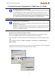
User Manual Managed Switches 2.1 Serial Console Configuration (115200, None, 8, 1, VT100) Note about simultaneously connections You cannot connect to the Ethernet Switch simultaneously by serial console and Telnet. You can connect to the Ethernet Switch simultaneously by web browser and serial console or by web browser and Telnet. However, we strongly suggest that you do NOT use more than one connection method at the same time.
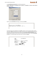
User Manual Managed Switches The Communication Parameter for console connection are: 115200 for Baud Rate, 8 for Data Bits, None for Parity, 1 for Stop Bits, and None for Flow control. Click OK to continue. Type 1 to select ansi/VT100 terminal type, and then press Enter. The Console login screen will appear. Press Enter to open the Account pop-up selector and then select either admin (read/write access) or user (read access only).
User Manual Managed Switches The Main Menu of the Switch´s serial console will be displayed. After entering the Main Menu, use the following keys to move the cursor, and to select options. Key Function Up/Down/Left/Right arrows, or Tab Move the onscreen cursor Enter Display & select options Space Toggle options Esc Previous Menu 2.
User Manual Managed Switches After making sure that the Weidmüller switch is connected to the same LAN and logical subnet as your PC, open the Weidmüller switch’s Telnet console as follows: Click Start Run from the Windows Start menu and then Telnet to the Weidmüller switch’s IP address from the Windows Run window. You may also issue the Telnet command from a DOS prompt. In the terminal window, the Telnet console will prompt you to select a terminal type.
User Manual Managed Switches After entering the Main Menu, use the following keys to move the cursor, and to select options. Key Function Up/Down/Left/Right arrows, or Tab Move the onscreen cursor Enter Display & select options Space Toggle options Esc Previous Menu NOTE: The Telnet Console looks and operates in precisely the same manner as the RS-232 Console. 2.3 Accessing configuration interface via Web Browser 2.3.
User Manual Managed Switches NOTE: Before accessing the Switch’s web browser interface, first connect one of its RJ45 Ethernet ports to your Ethernet LAN, or directly to your PC's Ethernet card (NIC). You can establish a connection with either a straight-through or cross-over Ethernet cable. NOTE: The Weidmüller switch’s default IP address is 192.168.1.110.
User Manual Managed Switches 2.3.2 Accessing the Webinterface via HTTPS This function is not implemented in the Weidmüller Ethernet Switch Family “Value Line”. To secure your HTTP access, the Weidmüller switch supports HTTPS/SSL to encrypt all HTTP traffic. Perform the following steps to access the Weidmüller switch web browser interface via HTTPS/SSL. Open Internet Explorer and enter https:// in the address field. Press Enter to establish the connection.
User Manual Managed Switches Select “Continue to this website” to enter the Weidmüller switch´s web browser interface and access the web browser interface secured via HTTPS/SSL. 2.4 Accessing configuration interface via SSL The console port can be accessed via a SSL/SSH connection using port 22. For configuration eg. a tool like PuTTY can be used. The procedure to configure the switch via SSL/SSH is the same as it has to be done for the serial interface.
User Manual Managed Switches 2.5 Disabling Telnet and Browser Access If you are connecting the Weidmüller Switch to a public network, but do not intend to use its management functions over the network, we suggest disabling both Telnet and Web consoles. This is done from the serial console by navigating to System Identification under Basic Settings.
User Manual Managed Switches 3. Featured Functions In this chapter, we explain how to access the Weidmüller Switch’s various configuration, monitoring, and administration functions. These functions can be accessed by serial, Telnet, or Web console. The serial console can be used if you do not know the Weidmüller Switch’s IP address and requires that you connect the Weidmüller switch to a PC´s COM port. The Telnet and web consoles can be opened over an Ethernet LAN or the Internet.
User Manual Managed Switches 3.1 Configuring Basic Settings The Basic Settings section includes the most common settings required by administrators to maintain and control a Weidmüller switch. 3.1.1 System Identification The system identification items are displayed at the top of the web page, and will be included in alarm emails. You can configure the System Identification items to make it easier to identify different switches that are connected to your network. Switch Name Setting Max.
User Manual Managed Switches characters contact this person. Web Auto-logout (sec) Setting Description Factory Default 60 to 86400 (seconds) Disable or extend the auto-logout time for the web management console. 0 (disabled) Age Time (sec) Setting Description Factory Default 15 to 3825 (seconds) The length of time that a MAC address entry can remain in the Weidmüller switch´s MAC address table.
User Manual Managed Switches NOTE: The Switch's default Password is ”Detmold”. If this Password is changed, then you will be required to type the new Password when logging into the serial console, Telnet console, or Web console. Account Setting Description admin This account can modify the Weidmüller switch’s configuration. user Factory Default admin This account can only view the Weidmüller switch’s configurations. Password Setting Description Factory Default Old password (max.
User Manual Managed Switches You may add or remove IP addresses to limit access to the Weidmüller switch. When the accessible IP list is enabled, only addresses on the list will be allowed access to the Weidmüller switch. Each IP address and netmask entry can be tailored for different situations: • Grant access to one host with a specific IP address For example, enter IP address 192.168.1.1 with netmask 255.255.255.255 to allow access to 192.168.1.1 only.
User Manual Managed Switches Enable Setting Description Factory Default Checked Allows data transmission through the port. Enabled Unchecked Immediately shuts off port access. NOTE: If a connected device or sub-network is wreaking havoc on the rest of the network, the Disable option gives the administrator a quick way to shut off access through this port immediately.
User Manual Managed Switches FDX Flow Ctrl This setting enables or disables flow control for the port when the port’s Speed is set to Auto. The final result will be determined by the Auto process between the Weidmüller switch and connected devices. Setting Description Factory Default Enable Enables flow control for this port when the port’s Speed is set to Auto. Disable Disables flow control for this port when the port’s Speed is set to Auto.
User Manual Managed Switches IP4 Settings The IPv4 settings include the switch’s IP address and subnet mask, as well as the IP address of the default gateway. In addition, input cells are provided for the IP addresses of a 1st and 2nd DNS server. Auto IP Configuration Setting Description Disable The Weidmüller switch’s IP address must be set manually. By DHCP The Weidmüller switch’s IP address will be assigned automatically by the network’s DHCP server.
User Manual Managed Switches Default Gateway Setting Description Factory Default IP address for the gateway The IP address of the router that connects the LAN to an outside network. None DNS IP Address Setting 1st DNS Server’s IP address Factory Default Description The IP address of the DNS Server used by your network. After entering the DNS Server's IP address, you can input the Weidmüller Switch's URL (e.g., www.VL08M.company.
User Manual Managed Switches Global Unicast Address Setting Factory Default Description Displays the IPv6 Global Unicast address. The network portion of the Global Unicast address can be configured by specifying the Global Unicast Prefix and using an EUI-64 interface ID in the low order 64 bits. The host portion of the Global Unicast address is automatically generated using the modified EUI-64 form of the interface identifier (Switch’s MAC address).
User Manual Managed Switches Join Time Setting Description Factory Default None Specifies the period of the join time 200 Setting Description Factory Default None Specifies the period of leave time 600 Leave Time Leaveall Time Setting Description Factory Default None Specifies the period of leaveall time 10000 NOTE Leave Time should be at least two times more than Join Time, and Leaveall Time should be larger than Leave Time. 3.1.7 Time 3.1.7.
User Manual Managed Switches The Weidmüller switch has a time calibration function based on information from an NTP server or user specified time and date. Functions such as automatic warning emails can therefore include time and date stamp. NOTE: The Weidmüller switch does not have a real time clock.
User Manual Managed Switches System Up Time Indicates how long the Weidmüller switch remained up since the last cold start. Time Zone Setting Description Factory Default User selectable time zone Specifies the time zone, which is used to determine the local time offset from GMT (Greenwich Mean Time). GMT (Greenwich Mean Time) NOTE: Changing the time zone will automatically correct the current time. Be sure to set the time zone before setting the time.
User Manual Managed Switches power systems. All devices ultimately get their time from a clock known as the grandmaster clock. In its basic form, the protocol is intended to be administration free.” How does an Ethernet switch affect 1588 synchronization? The following content is taken from the NIST website at http: //ieee1588.nist.gov/switch.htm: “An Ethernet switch potentially introduces multi-microsecond fluctuations in the latency between the 1588 grandmaster clock and a 1588 slave clock.
User Manual Managed Switches Configuring PTP IEEE 1588/PTP Operation Operation Setting Description Factory Default Enable PTP Globally disables or enables IEEE 1588 operation. Disabled Clock Mode (sets the switch’s clock mode) Setting Description Factory Default v1 BC Operates as an IEEE 1588 v1 boundary clock.
User Manual Managed Switches logSyncInterval (sets the synchronization message time interval) Setting Description Factory Default 0, 1, 2, 3, or 4 0 (1 s), 1 (2 s), 2 (4 s), 3 (8 s), or 4 (16 s). Supported in IEEE 1588 V1. 0 Setting Description Factory Default 0, 1, 2, 3, 4, or 5 Minimum delay request message interval 0 (1 sec.
User Manual Managed Switches 3.1.8 Turbo Ring DIP Switch (Menu item and DIP switches) The menu item Turbo Ring DIP Switch can be used as follows: Enable or disable the settings for Turbo Ring redundancy by the 4 DIP switches located on the top of the Switch housing. Selection of used redundancy protocol Turbo Ring V1 or Turbo Ring V2 if enabled in this menu. By default Turbo Ring V2 is activated and will be used when configuring Turbo Ring redundancy by DIP switches (as shown in above screenshot).
User Manual Managed Switches If DIP switch 4 is set to ON then the Webinterface menu ‘Communication Redundancy’ is locked, showing the selected Turbo Ring version. DIP switch 4 overrules the redundancy settings of the Webinterface. The role of the switch (Master yes/no, Coupler yes/no) will be set by DIP switches 2 and 3. Behavior of DIP Switch settings when protocol is set to ‘Turbo Ring V1’ DIP 1 DIP 2 DIP 3 ON: Enables this ON: Enables the SWITCH as the Ring default “Ring Master.
User Manual Managed Switches If you do not enable any of the managed Weidmüller Ethernet Switches to be the Ring Master, the Turbo Ring protocol will automatically choose the Ethernet Switch with the smallest MAC address range to be the Ring Master. If you accidentally enable more than one Ethernet Switch to be the Ring Master, these switches will auto-negotiate to determine which one will be the Ring Master.
User Manual Managed Switches Default Max. 40 characters Specifies the path and file name of the Weidmüller switch’s configuration file on the TFTP server. None Firmware Files Path and Name Setting Description Factory Default Max. 40 characters Specifies the path and file name of the Weidmüller switch’s firmware file. None Setting Description Factory Default Max. 40 characters Specifies the path and file name of the Weidmüller switch’s log file.
User Manual Managed Switches NOTE: Some operating systems will open the configuration file and log file directly in the web page. In such cases, right click the Export button to save the file. Upgrade Firmware To import a new firmware file into the Weidmüller switch, click Browse to select the firmware file that is saved on your computer. The upgrade procedure will proceed automatically after clicking Import.
User Manual Managed Switches Load the EBR-Module's configurations to the Switch To import the configuration file into the Weidmüller switch, click button Load to load it to the Switch. If you want to use an EBR-Module to import the configuration of Switch A (stored in the EBR-Module) into Switch B then both models must be of the same type. 3.1.10 Security The Security software function’s RADIUS and TACACS+ for user login authentication RADIUS for 802.
User Manual Managed Switches Server type TACACS+ Server type Radius Setting Description Factory Default Server Type Authentication server types selection TACACS+ Server IP/Name Set IP address of an external TACACS+/RADIUS server as the authentication database Localhost Server Port Set communication port of an external TACACS+/RADIUS server as the authentication database TACACS+ : 49 Server Shared Key Set specific characters for server authentication verification None Authentication Type Th
User Manual Managed Switches 3.1.10.2 Using Port Access Control The Weidmüller Premium Line switches provide two kinds of Port-Based Access Control: Static Port Lock IEEE 802.1X Static Port Lock In this case the Weidmüller switch can be configured to protect static MAC addresses for a specific port. With the Port Lock function, these locked ports will not learn any additional addresses, but only allow traffic from preset static MAC addresses, helping to block hackers and careless usage.
User Manual Managed Switches 1. When the supplicant receives an "EAP Request/Identity" frame, it sends an "EAP Response/Identity" frame with its username back to the authenticator. 2. If the RADIUS server is used as the authentication server, the authenticator relays the "EAP Response/Identity" frame from the supplicant by encapsulating it into a "RADIUS Access-Request" frame and sends to the RADIUS server.
User Manual Managed Switches Configuring Static Port Lock The Weidmüller switch supports adding unicast groups manually if required. Static Unicast MAC Address Setting Description Factory Default MAC Address Add the static unicast MAC address into the address table. None Port Associates the static address with a dedicated port. 1 Configuring IEEE 802.
User Manual Managed Switches (Max. 32 users) Database as the authentication database. Radius Select this option to set an external RADIUS server as the authentication database. The authentication mechanism is EAP-MD5. Local Radius, Local Select this option to make using an external RADIUS server as the authentication database the first priority. The authentication mechanism is EAP-MD5 The first priority is to set the Local User Database as the authentication database.
User Manual Managed Switches enable IEEE 802.1X for one or more ports. All end stations must enter usernames and passwords before access to these ports is allowed. 802.1X Re-Authentication The Weidmüller switch can force connected devices to be re-authorized manually. 802.1X Re-Authentication Setting Description Factory Default Enable/Disable Enables or disables 802.
User Manual Managed Switches Local User Database Setup Setting Description Factory Default User Name for the Local User Database None Password for the Local User Database None Description for the Local User Database None User Name (Max. 30 characters) Password (Max. 16 characters) Description (Max. 30 characters) NOTE: The user name for the Local User Database is case-insensitive.
User Manual Managed Switches Dot1X Radius Server Setting Same as Auth Server Setting Setting Description Factory Default Enable/Disable Enable to use the same setting as Auth Server Disable Setting Description Factory Default Server IP/Name Specifies the IP/name of the server localhost Server Port Specifies the port of the server 1812 Server Shared Key Specifies the shared key of the server None Server Setting Port Access Control Table The port status will indicate whether the access is
User Manual Managed Switches 3.1.11 Restart This function is used to restart the Ethernet Switch. 3.1.12 Factory Default This function provides users with a quick way of restoring the Weidmüller switch’s configuration to factory defaults. The function is available in the serial, Telnet, and web consoles. NOTE: After restoring the factory default configuration, you will need to use the default network settings to re-establish the web or Telnet console connection with the Weidmüller switch. 3.1.
User Manual Managed Switches 3.2 Using Port Trunking Port Trunking is only available for Weidmüller Premium Line managed switches. Link Aggregation allows one or more links to be aggregated together to form a Link Aggregation Group. A MAC client can treat Link Aggregation Groups as if they were a single link. The Weidmüller switch's Port Trunking feature allows devices to communicate by aggregating up to 4 trunk groups, with a maximum of 8 ports for each group.
User Manual Managed Switches After port trunking has been activated, you can configure these settings again for each trunking port. 3.2.1 Port Trunking Settings The Port Trunking Settings page is used to assign ports to a Trunk Group. Step 1: Select the desired Trunk Group (Trk1, Trk2, Trk3, Trk4) from the drop-down box . Step 2: Select Static, or LACP from the Trunk Type drop-down box. Step 3: Select the desired ports under Available Ports and click Up to add to the Trunk group.
User Manual Managed Switches Available Ports/Member Ports Setting Description Factory Default Member/Available ports Lists the ports in the current trunk group and the ports that are available to be added. N/A Check box Selects the port to be added or removed from the group. Unchecked Port Port number. N/A Port description Displays the media type for each port. N/A Name Displays the specified name for each port.
User Manual Managed Switches 3.3 Configuring SNMP Weidmüller managed Switches supports SNMP V1, V2c, and V3. SNMP V1 and SNMP V2c use a community string match for authentication, which means that SNMP servers access all objects with read-only or read/write permissions using the community strings public and private by default. SNMP V3 requires that you select an authentication level of MD5 or SHA, and is the most secure protocol. You can also enable data encryption to enhance data security.
User Manual Managed Switches 3.3.1 SNMP Read/Write Settings SNMP Versions Setting Description Factory Default Specifies the SNMP protocol version used to manage the switch.
User Manual Managed Switches Max. 30 characters Specifies the community string to authenticate the SNMP agent for read-only access. The SNMP agent will access all objects with read-only permissions using this community string. Public V1, V2c Write/Read Community Setting Description Factory Default Max. 30 characters Specifies the community string to authenticate the SNMP agent for read/write access. The SNMP server will access all objects with read/write permissions using this community string.
User Manual Managed Switches SHA-Auth Authentication will be based on the HMAC-SHA algorithms. 8-character passwords are the minimum requirement for authentication. No User Data Encryption Key (for SNMP V1, V2c, V3 and V3 only) Setting Description Factory Default Enable Enables data encryption using the specified data encryption key (between 8 and 30 characters). No Disable No data encryption No 3.3.
User Manual Managed Switches 1st Trap Server IP/Name Setting Description Factory Default IP or name Specifies the IP address or name of the primary trap server used by your network. None Setting Description Factory Default character string Specifies the community string to use for authentication (maximum of 30 characters).
User Manual Managed Switches 3.4 Using PoE (PoE Models Only) Power over Ethernet has become increasingly popular due in large part to the reliability provided by PoE Ethernet switches that supply the necessary power to Powered Devices (PD) when AC power is not readily available or cost-prohibitive to provide locally.
User Manual Managed Switches Port Setting Enable Setting Description Factory Default Checked Allows data and power transmission through the port Enable Unchecked Immediately shuts off port access Enable Setting Description Factory Default Auto The amount of power assigned is determined according to the class that is read from the powered device. Auto Manual The user can set the power limit value that indicates the maximum amount of power available to the port.
User Manual Managed Switches 3.4.2 PoE Timetabling Powered devices usually do not need to be running 24 hours a day, 7days a week. The PoE Ethernet switch provides a PoE timetabling mechanism to let users set a flexible working schedule for each PoE port to economize the system’s power burden.
User Manual Managed Switches Consumption (W) Indicates the actual Power consumed value for PoE port Voltage (V) Indicates the actual Voltage consumed value for PoE port Current (mA) Indicates the actual Current consumed value for PoE port 3.4.4 PoE Email Warning Events Settings Since industrial Ethernet devices are often located at the endpoints of a system, these devices do not always know what is happening elsewhere on the network.
User Manual Managed Switches 3.5 Communication redundancy 3.5.1 Introduction to Communication Redundancy Setting up Communication Redundancy on your network helps protect critical links against failure, protects against network loops, and keeps network downtime at a minimum. Communication Redundancy allows you to set up redundant loops in the network to provide a backup data transmission route in the event that a cable is inadvertently disconnected or damaged.
User Manual Managed Switches Note: Port trunking and Turbo Ring can be enabled simultaneously to form a backbone. Doing so will increase the bandwidth of the backbone, and also provide redundancy. For example, suppose that two physical ports, 1 and 2, are trunked to form trunk group Trk1, and then Trk1 is set as one Turbo Ring path. If eg. port 1 gets disconnected, the remaining trunked port 2 will share the traffic.
User Manual Managed Switches When the Number of Switches in the Turbo Ring (V1) is Even "Turbo Ring (V1)" with an even number of switches Master If there are 2N switches (an even number) in the "Turbo Ring", then the backup segment is one of the two segments connected to the (N+1) st switch (i.e., the switch unit directly opposite the master).
User Manual Managed Switches 3.5.2.2 Ring Coupling Configuration In some applicaions it may not be convenient to connect all devices in the system to form one large redundant ring, though some devices are located in a remote area. For these systems, “Ring Coupling” can be used to separate the devices into different smaller redundant rings, but in such a way that they can still communicate with each other.
User Manual Managed Switches Note that the ring coupling settings for a “Turbo Ring V2” are different from a “Turbo Ring”. For Turbo Ring V2, Ring Coupling is enabled by configuring the “Coupling Port” (Primary) on Switch B, and the “Coupling Port” (Backup) on Switch A only. You do not need to set up a coupling control port, so that a “Turbo Ring V2” does not use a coupling control line.
User Manual Managed Switches Dual-Homing for a "Turbo Ring V2" Master Primary Path Ring A Ring B Backup Path Master 3.5.3 Configuring “Turbo Ring (V1)” and “Turbo Ring V2” Use the Communication Redundancy page to select “Turbo Ring (V1)”, “Turbo Ring V2”, or “Turbo Chain”. Note that configuration pages for these three protocols are different. 3.5.3.1 Configuring Turbo Ring (V1, original version) 1. Select Turbo Ring in field Redundancy protocol. 2.
User Manual Managed Switches Explanation of “Current Status” Items Now Active It shows which communication protocol is in use: RSTP, Turbo Ring( V1), Turbo Ring V2, Turbo Chain or none. Master/Slave It indicates whether this switch is the Master (or not) of the Turbo Ring. This field appears only when Turbo Ring or Turbo Ring V2 modes are selected. NOTE: The user does not need to set the master to use Turbo Ring.
User Manual Managed Switches Coupling Control Port Setting Coupling Control Port Description Factory Default Select any port of the switch to be the coupling control See the following port table Below table lists the default coupling ports dependent on the used models.
User Manual Managed Switches NOTE: When using the Dual-Ring architecture, users must configure settings for both Ring 1 and Ring 2. In this case, the status of both rings will appear under “Current Status.” Explanation of “Current Status” Items Now Active It shows which communication protocol is in use: Turbo Ring, Turbo Ring V2, Turbo Chain, RSTP, or none. Ring 1/2—Status It shows Healthy if the ring is operating normally, and shows Break if the ring’s backup link is active.
User Manual Managed Switches Explanation of ‘Setting’ items for selected redundancy protocol Turbo Ring V2 Enable Ring 1 Setting Enabled Disabled Description Enable the Ring 1 settings Disable the Ring 1 settings Factory Default checked Not checked Description Enable the Ring 2 settings Disable the Ring 2 settings Factory Default Enable Ring 2 Setting Enabled Disabled Not checked Set as Master Setting Enabled Disabled Description Select this Switch as Master Do not select this Switch as Master Fac
User Manual Managed Switches (backup) Ring Coupling (primary) configuration page table Select this item to change to the Ring Coupling (primary) See the following configuration page table Below table lists the default coupling ports dependent on the used models. Model All models Default Dual Homing (Primary) Default Dual Homing (Backup) Port 1 Port 2 NOTE: The Turbo Ring DIP switches, located on top of the housing, alternatively can be used to configure the Turbo Ring protocols.
User Manual Managed Switches 3.5.4 The Turbo Chain Concept Turbo Chain is an advanced software-technology that gives network administrators the flexibility of constructing any type of redundant network topology. When using the “Turbo Chain” concept, you first connect the Ethernet switches in a chain and then simply link the two ends of the chain to an Ethernet network, as illustrated in the following figure. Turbo Chain can be used on industrial networks that have a complex topology.
User Manual Managed Switches packets are transmitted through the Head Port to the attached network. If any Turbo Chain path is disconnected, the Tail Port will be activated so that packet transmission can continue. There is no need to change anything in the configuration of the network on which the Turbo Chain switches will be attached. 3.5.5.1 Head Switch Configuration 3.5.5.2 Member Switch Configuration 3.5.5.
User Manual Managed Switches Explanation of “Current Status” Item Now Active It shows which communication protocol is in use: Turbo Ring V1, Turbo Ring V2, RSTP, Turbo Chain, or None. The “Ports Status” indicators show Forwarding for normal transmission, Blocked if this port is connected to the Tail port as a backup path and the path is blocked, and Link down if there is no connection.
User Manual Managed Switches IE-SW-VL05M/08M Series IE-SW-PL06M/08M/09M/16M Series IE-SW-PL18M Series IE-SW-PL10M Series The second port from the last port The last port of the switch (highest number port number) Port G1 Port G2 Port G2 Port G3 3.5.6 STP / RSTP 3.5.6.1 The STP / RSTP Concept Spanning Tree Protocol (STP) was designed to help reduce link failures on a network, and provide an automatic means of avoiding loops.
User Manual Managed Switches L A N Bridge B Bridge A 1 L A N Bridge C 2 L A N If STP is enabled, it will detect duplicate paths and prevent, or block, one of the paths from forwarding 3 traffic. In the following example, STP determined that traffic from LAN segment 2 to LAN segment 1 should flow through bridges C and A since this path has a greater bandwidth and is therefore more efficient.
User Manual Managed Switches STP will determine which path between each bridged segment is most efficient, and then assign a specific reference point on the network. When the most efficient path has been identified, the other paths are blocked. In the previous 3 figures, STP first determined that the path through bridge C was the most efficient, and as a result, blocked the path through bridge B. After the failure of bridge C, STP re-evaluated the situation and opened the path through Bridge B. 3.5.6.
User Manual Managed Switches transmitted in the direction of the Root Bridge will flow through the Designated Bridge. The port on this bridge that connects to the segment is called the Designated Bridge Port. STP Configuration After all of the bridges on the network agree on the identity of the Root Bridge, and all other relevant parameters have been established, each bridge is configured to forward traffic only between its Root Port and the Designated Bridge Ports for the respective network segments.
User Manual Managed Switches Bridge A has been selected as the Root Bridge, since it was determined to have the lowest Bridge Identifier on the network. Since Bridge A is the Root Bridge, it is also the Designated Bridge for LAN segment 1. Port 1 on Bridge A is selected as the Designated Bridge Port for LAN Segment 1. Ports 1 of Bridges B, C, X, and Y are all Root Ports since they are nearest to the Root Bridge, and therefore have the most efficient path.
User Manual Managed Switches To avoid subdividing VLANs, all inter-switch connections should be made members of all available 802.1Q VLANs. This will ensure connectivity at all times. For example, the connections between switches A and B, and between switches A and C, should be 802.1Q tagged and carrying VLANs 1 and 2 to ensure connectivity. 3.5.7 Configuring STP / RSTP The following figures indicate which Spanning Tree Protocol parameters can be configured.
User Manual Managed Switches At the top of this page, the user can check the Current Status of this function. For RSTP, you will see: Root/Not Root This field only appears when RSTP mode is selected. The field indicates whether or not this switch is the Root of the Spanning Tree (the root is determined automatically). At the bottom of this page, the user can configure the “Settings” of this function.
User Manual Managed Switches NOTE: We suggest not enabling the Spanning Tree Protocol once the port is connected to a device (PLC, RTU, etc.) as opposed to network equipment. The reason is that it will cause unnecessary negotiation. Edge Port Setting Auto Force Edge False Description Factory Default 1. If the port does not receive a BPDU within 3 seconds, the port will be in the forwarding state. 2. Once the port receives a BPDU, it will start the RSTP negotiation process.
User Manual Managed Switches 2 x (Forwarding Delay – 1 sec) = 6 sec. You can remedy the situation in many ways. One solution is simply to increase the Forwarding Delay value to at least 11 sec. Perform the following steps to avoid repetitive approach: Step 1: Assign a value to “Hello Time” and then calculate the left most part of rule 4 to get the lower limit of “Max. Age”. Step 2: Assign a value to “Forwarding Delay” and then calculate the right most part of rule 4 to get the upper limit for “Max. Age”.
User Manual Managed Switches Traffic prioritization uses the four traffic queues that are present in your Weidmüller managed Switch to ensure that high priority traffic is forwarded on a different queue from lower priority traffic. This is what provides Quality of Service (QoS) to your network. Weidmüller managed Switch traffic prioritization depends on two industry-standard methods: IEEE 802.1D A layer 2 marking scheme. Differentiated Services (DiffServ) A layer 3 marking scheme. IEEE 802.
User Manual Managed Switches DiffServ is a Layer 3 marking scheme that uses the DiffServ Code Point (DSCP) field in the IP header to store the packet priority information. DSCP is an advanced intelligent method of traffic marking that allows you to choose how your network prioritizes different types of traffic. DSCP uses 64 values that map to user-defined service levels, allowing you to establish more control over network traffic. The advantages of DiffServ over IEEE 802.
User Manual Managed Switches Strict: This method services high traffic queues first; low priority queues are delayed until no more high priority data needs to be sent. The Strict method always gives precedence to high priority over low priority. 3.6.2 Configuring Traffic Prioritization Quality of Service (QoS) provides a traffic prioritization capability to ensure that important data is delivered consistently and predictably. The Weidmüller switch can inspect IEEE 802.
User Manual Managed Switches Queuing Mechanism – Type 1 Factory Default Setting Description Weight Fair The Weidmüller switch has 4 priority queues. In the weight fair scheme, an 8, 4, 2, 1 weighting is applied to the four priorities. This approach prevents the lower priority frames from being starved of opportunity for transmission with only a slight delay to the higher priority frames.
User Manual Managed Switches Queuing Mechanism – Type 2 Factory Default Setting Description Weight Fair The Weidmüller switch has 4 priority queues. In the weight fair scheme, an 8, 4, 2, 1 weighting is applied to the four priorities. This approach prevents the lower priority frames from being starved of opportunity for transmission with only a slight delay to the higher priority frames.
User Manual Managed Switches Inspect COS – Type 2 Setting Description Factory Default Enable/Disable Enables or disables the Weidmüller Switch for inspecting 802.1p COS tags in the MAC frame to determine the priority of each frame. Enabled NOTE: The designer can enable these classifications individually or in combination. For instance, if a “hot” higher priority port is required for a network design, “Inspect TOS” and “Inspect CoS” can be disabled.
User Manual Managed Switches ToS (DSCP) Value and Priority Queues Setting Description Factory Default Low/Normal/ Medium/High Maps different ToS values to 4 different egress queues.. 1 to 16: Low 17 to 32: Normal 33 to 48: Medium 49 to 64: High 3.7 Using Virtual LAN Setting up Virtual LANs (VLANs) on your Weidmüller switch increases the efficiency of your network by dividing the LAN into logical segments, as opposed to physical segments. In general, VLANs are easier to manage. 3.7.
User Manual Managed Switches Switch A 1 2 3 4 5 6 7 8 Backbone connects multiple switches Switch B 1 2 3 4 5 6 7 8 Department 1 VLAN 1 Department 3 Department 2 VLAN 3 VLAN 2 Benefits of VLANs The main benefit of VLANs is that they provide a network segmentation system that is far more flexible than traditional networks.
User Manual Managed Switches Communication between VLANs If devices connected to a VLAN need to communicate to devices on a different VLAN, a router or Layer 3 switching device with connections to both VLANs needs to be installed. Communication between VLANs can only take place if they are all connected to a routing or Layer 3 switching device. VLANs: Tagged and Untagged Membership The Weidmüller switch supports 802.
User Manual Managed Switches In this application, Port 1 connects a single untagged device and assigns it to VLAN 5; it should be configured as "Access Port" with PVID 5. Port 2 connects a LAN with two untagged devices belonging to VLAN 2. One tagged device with VID 3 and one tagged device with VID 4. It should be configured as "Trunk Port" with PVID 2 for untagged device and Fixed VLAN (Tagged) with 3 and 4 for tagged device.
User Manual Managed Switches 3.7.2 Configuring Virtual LAN 3.7.2.1 VLAN Settings To configure 802.1Q VLAN and port-based VLANs on the Weidmüller switch, use the VLAN Settings page to configure the ports. VLAN Mode Setting Description Factory Default 802.1Q VLAN Set VLAN mode to 802.1Q VLAN 802.1Q VLAN Port-based VLAN Set VLAN mode to Port-based VLAN Management VLAN ID Setting Description Factory Default VLAN ID from 1 to 4094 Assigns the VLAN ID of the Weidmüller switch.
User Manual Managed Switches Access This port type is used to connect single devices without tags. Trunk Select "Trunk" port type to connect another 802.1Q VLAN aware switch. Hybrid Select Hybrid port to connect another Access 802.1Q VLAN aware switch or another LAN that combines tagged and/or untagged devices and/or other switches/hubs.
User Manual Managed Switches supported by this trunk port. Use commas to separate different VIDs. 3.7.2.2 Port-Based VLAN Settings Check each specific port to assign its VLAN ID in the table. The maximum VLAN ID is the same as your number of switch ports. Port Setting Description Factory Default Enable/Disable Set port to specific VLAN Group by activating checkbox. Enable 3.7.2.
User Manual Managed Switches In 802.1Q VLAN table, you can review the VLAN groups that were created, Joined Access Ports, Trunk Ports and Hybrid Ports. In Port-based VLAN table, you can review the VLAN group and joined ports. NOTE: The Weidmüller managed switches have a maximum of 64 VLAN settings. 3.
User Manual Managed Switches Multicast filtering improves the performance of networks that carry multicast traffic. This section explains multicasts, multicast filtering, and how multicast filtering can be implemented on your Weidmüller switch. 3.8.1 The Concept of Multicast Filtering What is an IP Multicast? A multicast is a packet sent by one host to multiple hosts. Only those hosts that belong to a specific multicast group will receive the multicast.
User Manual Managed Switches Network without multicast filtering All hosts receive the multicast traffic, even if they don’t need it. Network with multicast filtering Hosts only receive dedicated traffic from other hosts belonging to the same group. The Weidmüller switch has three ways to achieve multicast filtering: IGMP (Internet Group Management Protocol) Snooping, GMRP (GARP Multicast Registration Protocol), and adding a static multicast MAC manually to filter multicast traffic automatically.
User Manual Managed Switches Snooping Mode Snooping Mode allows your switch to forward multicast packets only to the appropriate ports. The switch "snoops" on exchanges between hosts and an IGMP device, such as a router, to find those ports that want to join a multicast group, and then configure its filters accordingly. IGMP Snooping Enhanced Mode Snooping Enhanced Mode allows your switch to forward multicast packets to the Weidmüller switch member port only.
User Manual Managed Switches IGMP Version Main Features Reference V1 Periodic query RFC-1112 V2 Compatible with V1 and adds: RFC-2236 • Group-specific query • Leave group messages • Resends specific queries to verify leave message was the last one in the group • Querier election GMRP (GARP Multicast Registration Protocol) Weidmüller managed switches support IEEE 802.1D-1998 GMRP (GARP Multicast Registration Protocol), which differs from IGMP (Internet Group Management Protocol).
User Manual Managed Switches IGMP Snooping Enable Setting Description Factory Default Enable/Disable Checkmark the IGMP Snooping Enable checkbox to enable the IGMP Snooping function globally. Disabled Setting Description Factory Default Numerical value, input by the user Sets the query interval of the Querier function globally. Valid settings are from 20 to 600 seconds.
User Manual Managed Switches Querier Setting Description Factory Default Enable/Disable Select the option to enable the querier function. Enabled if IGMP Snooping is enabled globally Static Multicast Querier Port Setting Description Factory Default Select/Deselect Select the ports that will connect to the multicast routers. These ports will receive all multicast packets from the source. This option is only active when IGMP Snooping is enabled.
User Manual Managed Switches 3.8.4 Static Multicast MAC Addresses If required, the Weidmüller switch also supports adding multicast groups manually. Add New Static Multicast Address to the List Setting Description Factory Default MAC Address Input the multicast MAC address of this host. None MAC Address Setting Description Factory Default Integer Input the number of the VLAN that the host with this MAC address belongs to.
User Manual Managed Switches 3.8.5 Configuring GMRP GMRP is a MAC-based multicast management protocol, whereas IGMP is IP-based. GMRP provides a mechanism that allows bridges and end stations to register or un-register Group membership information dynamically. GMRP enable Setting Description Factory Default Enable/Disable Select the option to enable the GMRP function for the port listed in the Port column Disable 3.8.
User Manual Managed Switches 3.9 Using Bandwidth Management In general, one host should not be allowed to occupy unlimited bandwidth, particularly when the device malfunctions. For example, so-called “broadcast storms” could be caused by an incorrectly configured topology, or a malfunctioning device.
User Manual Managed Switches Policy Description Limit All Select the ingress rate limit for different packet types from the following options: Not Limited, 128K, 256K, 512K, 1M, 2M, 4M, 8M Limit Broadcast, Multicast, Flooded Unicast Limit Broadcast, Multicast Limit Broadcast Factory Default Limit Broadcast 8M Egress Rate Limit –Normal – Type 1 Egress Rate Limit –Normal – Type 1 Setting Description Factory Default Egress rate Select the egress rate limit (% of max.
User Manual Managed Switches Setting Description Factory Default Port disable duration (1~65535 seconds) When the ingress multicast and broadcast packets exceed the ingress rate limit, the port will be disabled for this period of time. During this time, all packets from this port will be discarded.
User Manual Managed Switches 3.9.
User Manual Managed Switches Ingress Rate Limit – Port Disable Setting Description Factory Default Period (1 ~ 65535 seconds) When the ingress packets exceed the ingress rate limit, the port will be disabled for a certain period. 30 seconds Ingress (frame per second) Select the ingress rate (fps) limit for all packets from the following options: Not limited, 4464, 7441, 14881, 22322, 37202, 52084, 74405 Not limited 3.
User Manual Managed Switches 3.10.2 Event Types Event Types can be divided into two basic groups: System Events and Port Events. System Events are related to the overall function of the switch, whereas Port Events are related to the activity of a specific port. System Events Warning e-mail is sent when… Switch Cold Start Power is cut off and then reconnected. Switch Warm Start Weidmüller switch is rebooted, such as when network parameters are changed (IP address, subnet mask, etc.).
User Manual Managed Switches Traffic-Overload The port’s traffic surpasses the Traffic-Threshold for that port (provided this item is Enabled). Traffic-Threshold (%) Enter a non-zero number if the port’s Traffic-Overload item is Enabled. (0 to 100 %) Traffic-Duration (sec.) (1 to 300 sec.) A Traffic-Overload warning is sent every Traffic-Duration seconds if the average Traffic-Threshold is surpassed during that time period.
User Manual Managed Switches Mail Server IP/Name Setting Description Factory Default IP address or name The IP Address or name of your email server. None Setting Description Factory Default SMTP port Display the SMTP port number 25 Setting Description Factory Default Max.
User Manual Managed Switches NOTE: Auto warning e-mail messages will be sent through an authentication protected SMTP server that supports the CRAM-MD5, LOGIN, and PAIN methods of SASL (Simple Authentication and Security Layer) authentication mechanism. We strongly recommend not entering your Account Name and Account Password if auto warning e-mail messages can be delivered without using an authentication mechanism. 3.10.
User Manual Managed Switches Power Transition (On -> Off) Weidmüller switch is powered down Power Transition (Off -> On) Weidmüller switch is powered up DI1 (OnOff) Digital Input 1 is triggered by on to off transition DI1 (OffOn) Digital Input 1 is triggered by off to on transition DI2 (OnOff) Digital Input 2 is triggered by on to off transition DI2 (OffOn) Digital Input 2 is triggered by off to on transition Turbo Ring Break The Turbo Ring is broken.
User Manual Managed Switches 3.11 Line-Swap-Fast-Recovery The Line-Swap Fast Recovery function, which is enabled by default, allows the Weidmüller switch to return to normal operation extremely quickly after devices are unplugged and then re-plugged into different ports. The recovery time is on the order of a few milliseconds (compare this with standard commercial switches for which the recovery time could be on the order of several minutes).
User Manual Managed Switches address. Take the following steps to use the Set device IP function: STEP 1 Set up the connected devices Set up those Ethernet-enabled devices connected to the Weidmüller switch for which you would like IP addresses to be assigned automatically. The devices must be configured to obtain their IP address automatically. The devices’ configuration utility should include a setup page that allows you to choose an option similar to the Obtain an IP address automatically option.
User Manual Managed Switches Desired IP Address Setting Description Factory Default IP Address Set the desired IP of connected devices. None 3.12.2 DHCP Relay Agent (Option 82) The DHCP Relay Agent makes it possible for DHCP broadcast messages to be sent over routers. The DHCP Relay Agent enables DHCP clients to obtain IP addresses from a DHCP server on a remote subnet, or those that are not located on the local subnet.
User Manual Managed Switches Configuring DHCP Relay Agent Server IP Address 1st Server Setting Description Factory Default IP address for the 1st DHCP server Assigns the IP address of the 1st DHCP server that the switch tries to access. None Setting Description Factory Default IP address for the 2nd DHCP server Assigns the IP address of the 2nd DHCP server that the switch tries to access.
User Manual Managed Switches DHCP Option 82 Enable Option 82 Setting Description Factory Default Enable or Disable Enable or disable the DHCP Option 82 function. Disable Setting Description Factory Default IP Uses the switch’s IP address as the remote ID sub. IP MAC Uses the switch’s MAC address as the remote ID sub. IP Client-ID Uses a combination of the switch’s MAC address and IP address as the remote ID sub. IP Other Uses the user-designated ID sub.
User Manual Managed Switches 3.13 Using Diagnosis The Weidmüller switch provides three important tools for administrators to diagnose network systems. 3.13.1 Mirror Port The Mirror port function can be used to monitor data being transmitted through a specific port. This is done by setting up another port (the mirror port) to receive the same data being transmitted from, or both to and from, the port under observation.
User Manual Managed Switches When using the Console interface, activate by first highlighting the Activate menu option, and then press Enter. You should receive the Mirror port settings are now active! (Press any key to continue) message. 3.13.2 Ping The Ping function uses the ping command to give users a simple but powerful tool for troubleshooting network problems.
User Manual Managed Switches From the switch's web interface, users have the option of either enabling or disabling the LLDP, as well as setting the LLDP transmit interval (as shown in the figure below). In addition, users are able to view each switch's neighbor-list, which is reported by its network neighbors.
User Manual Managed Switches 3.14 Using Monitor You can monitor statistics in real time from the Weidmüller switch’s web console and serial console. 3.14.1 Monitor by Switch Access the Monitor by selecting "System" from the left selection bar. Monitor by System allows the user to view a graph that shows the combined data transmission activity of all of the switch's ports.
User Manual Managed Switches graph is updated every few seconds, allowing the user to analyze data transmission activity in real-time. 3.14.3 Monitor by SFP Optical fiber is commonly used for long distance data transmission. However, when link issues occur, it is very costly to trouble shoot the fiber cable and fiber transceiver at remote sites.
User Manual Managed Switches NOTE: Certain tolerances exist between real data and measured data. Parameters Tolerance Temperature (°C) ± 3°C Voltage (V) ± 0.1V Tx power (dBm) ± 3dB Rx power (dBm) ± 3dB 3.15 Using the MAC Address Table This section explains the information provided by the Weidmüller switch’s MAC address table.
User Manual Managed Switches This field shows the port that this MAC address belongs to. Port 3.16 System Log The following events will be recorded into the Switch’s Event Log table: Cold start Warm start Configuration change activated Power 1/2 transition (Off On), Power 1/2 transition (On Off) Authentication fail Topology changed Master setting is mismatched Port traffic overload dot1x Auth Fail Port link off/on 3.16.
User Manual Managed Switches 3.16.2 Syslog Settings This function provides the event logs for the syslog server. The function supports 3 configurable syslog servers and syslog server UDP port numbers. When an event occurs, the event will be sent as a syslog UDP packet to the specified syslog servers. The log data which will be sent to a syslog server is the same as created for the internal Event Log.
User Manual Managed Switches 4. Using Industrial Protocols 4.1 MODBUS/TCP MAP Introduction MODBUS TCP is a protocol commonly used for the integration of a SCADA system. It is also a vendor-neutral communication protocol used to monitor and control industrial automation equipment such as PLCs, sensors, and meters. In order to be fully integrated into industrial systems, Weidmüller’s switches support Modbus TCP/IP protocol for real-time monitoring in a SCADA system.
User Manual Managed Switches The data map addresses of Weidmüller switches shown in the following table start from MODBUS address 30001 for Function Code 4. For example, the address offset 0x0000 (hex) equals MODBUS address 30001, and the address offset 0x0010 (hex) equals MODBUS address 30017. Note that all the information read from Weidmüller switches are in hex mode. To interpret the information, refer to the ASCII table for the translation (e.g. 0x4D = ‘M’, 0x6F = ‘o’).
User Manual Managed Switches 0x0058 1 word 0x0059 1 word 0x005A 1 word 0x0082 1 word 0x1000 to 0x1011 1 word 0x1100 to 0x1111 1 word 0x1200 to 0x1211 1 word 0x1300 to 0x1311 1 word 0x1400 to 0x1413 (Port 1) 20 words 0x1414 to 0x1427 (Port 2) 0x2000 to 0x2023 2 words 0x2100 to 0x2123 2 words Word 1 Hi byte = 0 x 02 Word 1 Lo byte = 0 x 03 Word 2 Hi byte = 0 x 04 Word 2 Lo byte = 0 x 05 HEX Power 1 0x0000: Off 0x0001: On HEX Power 2 0x0000: Off 0x0001: On HEX Fault LED Status 0x0000: N
User Manual Managed Switches 0x2200 to 0x2223 2 words 0x2300 to 0x2323 2 words 0x3000 1 word 0x3100 1 word 0x3200 to 0x3211 1 word 0x3300 1 word 0x3301 1 word 0x3302 1 word 0x44332211 Word 0 = 4433 Word 1 = 2211 HEX port 1 to 8 Tx Error Packets Ex: port 1 Tx Error Packet Amount = 44332211 Received MODBUS response: 0x44332211 Word 0 = 4433 Word 1 = 2211 HEX port 1 to 8 Rx Error Packets Ex: port 1 Rx Error Packet Amount = 44332211 Received MODBUS response: 0x44332211 Word 0 = 4433 Word 1 = 22
User Manual Managed Switches 0x3303 1 word HEX 0x3304 1 word HEX 0x3305 1 word HEX 0x3500 1 word HEX 0x3501 1 word HEX 0x3502 1 word HEX 0x3600 1 word HEX 0x3601 1 word HEX 0x0005:Forwarding TurboRing Coupling 0x0000: Off 0x0001: On 0xFFFF: Turbo Ring is Not Enabled TurboRing Coupling Port Status 0x0000: Port Disabled 0x0001: Not Coupling Port 0x0002: Link Down 0x0003: Blocked 0x0005: Forwarding 0xFFFF: Turbo Ring is Not Enabled TurboRing Coupling Control Port Status 0x0000: Port Di
User Manual Managed Switches 0x3602 1 word HEX 0x3603 1 word HEX 0x3680 1 word HEX 0x3681 1 word HEX 0x3682 1 word HEX 0x3683 1 word HEX 0x3700 1 word HEX 0x3701 1 word HEX 0xFFFF: Turbo Ring V2 Ring 1 Not Enable TurboRing V2 Ring 1 1st Port Status 0x0000: Port Disabled 0x0001: Not Redundant Port 0x0002: Link Down 0x0003: Blocked 0x0004:Learning 0x0005:Forwarding 0xFFFF:Turbo Ring V2 Ring 1 is Not Enabled TurboRing V2 Ring 1’s 2nd Port Status 0x0000: Port Disabled 0x0001: Not Redund
User Manual Managed Switches 0x3702 1 word 0x0000: Link Down 0x0001: Blocking 0x0002: Blocked 0x0003: Forwarding 0xFFFF: Turbo Ring V2 Ring 2 Not Enable Turbo Chain 2nd Port status 0x0000: Link Down 0x0001: Blocking 0x0002: Blocked 0x0003: Forwarding 0xFFFF: Turbo Ring V2 Ring 2 Not Enable HEX 133
User Manual Managed Switches 4.2 Profinet I/O Introduction PROFINET is a communication standard for automation of PROFIBUS & PROFINET International (PI). It is 100% Ethernet-compatible as defined in IEEE standards. With PROFINET, applications can be implemented for production and process automation, safety applications, and the entire range of drive technology.
User Manual Managed Switches PROFINET I/O Devices The Weidmüller switch is a PROFINET I/O device. A device model describes all field devices in terms of their possible technical and functional features. It is specified by the DAP (Device Access Point) and the defined modules for a particular device family. A DAP is the access point for communication with the Ethernet interface and the processing program.
User Manual Managed Switches 5. Select Enable option and click Activate to enable PROFINET I/O. The PROFINET type LLDP will be enabled automatically when PROFINET I/O is enabled. Select the Disable option and click Activate to disable PROFINET I/O. The switch will disable PROFINET type LLDP and will use then standard LLDP. PROFINET I/O functionality is implemented in firmware version 3.3.x and later. If you use a managed Switch with firmware version 2.x you can update the firmware to latest version 3.3.x.
User Manual Managed Switches 4.2.4 Overview of Operation Procedure The following steps show how to integrate the switch into a PROFINET network: 1. Activate PROFINET protocol on the switch Enable checkbox PROFINET in switch web UI 2. Create a PROFINET I/O subnet project in STEP 7 Create a PROFINET I/O Ethernet project for deploying environment 3. GSD file installation Import Weidmüller switch GSD into the project 4. Device configuration Search and discover the switch in STEP 7.
User Manual Managed Switches Insert a station in your project by... Right click in category column > Insert New Object > your PLC series (here we select SIMATIC 300 station). Then you can see the new object in the project. Double click on the Hardware. After double-clicking on HW, you will see the HW Config window.
User Manual Managed Switches Drag a rack from the side bar to main dashboard. Click Rack-300 and drag Rail to the main screen. Add PLC CPU in HW Config Select your PLC CPU and drag it to the rack slot 2. Please select by PLC you used. Here we will select 6ES7-317-2EK14-0AB0 V3.2. Now, the Ethernet interface dialog will pop out. Fill your PLC IP address in “IP address” column. Then click New in subnet to create a new Ethernet subnet. Here we will create a subnet named “PROFINET Ethernet”, then click OK.
User Manual Managed Switches PROFINET I/O Ethernet subnet project now is accomplished. 4.2.6 GSD File Installation 1. Start SIMATIC manager on your PC. 2. Open your project. 3. Open hardware configuration.
User Manual Managed Switches Installing the GSD file 4. Put the GSD file and icon file on your PC at the same folder. 5. Click Options > Install GSD File 6. Click button Browse...
User Manual Managed Switches When the GSD file successfully is installed, you will find Weidmüller switches in the side bar under: PROFINET IO > Additional Field Devices > Network Components > Weidmueller Switch series 7. Select the Weidmüller switch from the side bar (in this case V3.3) and use Drag & Drop to pull the switch onto the bus cable. Then you can see the Weidmüller switch icon displayed on the screen. 4.2.7 Device Configuration Browse the switch 1.
User Manual Managed Switches 2. When the Edit Ethernet Node dialog box appears, click Browse 3. Select your target switch and click OK 4. Assign IP address and Device name to the switch Give the switch an IP address and subnet mask (e.g. 192.168.0.110, 255.255.255.0) Click Assign IP configuration Give the switch a name (e.g. IE-SW-VL08MT-8TX) Click Assign Name Click Close to finish NOTE The field Device name does not allow any empty spaces in the name.
User Manual Managed Switches 5. Set IP address and device name in your project Double-click the switch icon to open switch property menu. Set the Device name corresponding with those you have just assigned under section “Edit Ethernet Node”. (e.g. IE-SW-VL08MT-8TX) Click Ethernet… and set manually the IP address corresponding with those you have just assigned in STEP 7 (e.g. 192.168.0.
User Manual Managed Switches 6. Click Save and Compile in the Hardware configuration. 4.2.8 Configuring device properties 1. Select the switch and double-click the first sub-module slot 0 to set device properties. 2. Select Parameters and change the device parameter settings. 3. Click Save and Compile Configuring I/O cycle time 1. Select the switch and double-click the sub-module X1 to set the I/O cycle. 2. Select IO Cycle and change the I/O cycle settings. 3. Click Save and Compile.
User Manual Managed Switches 1. Select the switch and double-click the sub-module X1 P1 to set port property for Port 1. 2. Select Parameters and change the port parameters settings. 3. Click Save and Compile Configuring connection options 1. Select the switch and double-click the sub-module X1 P1 to set port options for Port 1. 2. Select Options and change the port option settings. 3. Click Save and Compile 4.2.
User Manual Managed Switches The PROFINET I/O connection can be configured for both cyclic I/O data and I/O parameters. I/O parameters are acyclic I/O data. These are major setup and monitor attributes in PROFINET. Cyclic I/O Data Cyclic I/O data are always sent between the PLC and Switches at the specified periodic time. These data are transmitted almost real time. For example, status information from the Switches, and variables to be written to the Switch would typically be part of the cyclic data.
User Manual Managed Switches connected Monitor PROFINET I/O Cyclic Data Weidmüller switches provide PROFINET I/O cyclic data for real-time monitoring. In side bar you can see Device data and Port data. To monitor Device data, use Drag & Drop to pull the Device data onto slot 1. Right-click on slot 1, then select Monitor/Modify. Use Monitor to check the input data value. In this dialog, select Monitor and then, you can see the status value of each address.
User Manual Managed Switches To monitor Port data, follow the same steps, drag Port data in the side bar and drop it onto slot 2. Then right click on slot 2 and select Monitor/Modify. You will see a monitoring window. Please refer to the PROFINET Cyclic I/O data table to see the meaning of each bit. For example, address 1.3 is set to Bit 1. It represents the connection status of Port 4 of the switch.
User Manual Managed Switches The module information dialog will then pop up. Port Statistics Output Select Statistics tab. Find out each port traffic information list below. The Statistics tab lists each port traffic status and the number of packets. Click Update to refresh the data. 4.2.11 I/O Device Diagnostics Weidmüller PROFINET switches support PROFINET alarms. These alarm messages will be sent by the switch immediately when an event is triggered.
User Manual Managed Switches Select Network Connection Diagnosis tab to view the connection status. 4.2.12 Topology Editor Weidmüller switches support SIMATIC STEP 7 Topology editor. Select Weidmüller switch Icon on the screen, then right click on PROFINET IO Topology. All port’s status will be displayed in table view tab.
User Manual Managed Switches In the Offline/Online Comparison tab, you can compare device partner ports. Click Start to discover connection relationships. Select the every connected port in the online topology window and click Apply button to confirm the device partner ports. After compared devices partner ports in the Offline/Online Comparison tab, click Graphic view to display the network topology. You can also draw the connection of each port manually in Graphic view tab.
User Manual Managed Switches 4.2.13 PROFINET I/O Parameters Weidmüller defines comprehensive PROFINET I/O parameters for more flexible settings and monitoring. There attributes are readable or writable. PROFINET I/O parameters use PROFINET acyclic data to achieve communication in the network. You can use the SIMATIC STEP 7 tool or engineering deployment software to edit it. There are 3 categories of parameters, including Device Parameters, Device Status and Port Parameters.
User Manual Managed Switches 4 5 6 7 8 9 10 11 12 13 DI 1 Status DI 2 Status Redundant Mode Ring Status Redundant Port 1 Status Redundant Port 2 Status Ring Coupling Mode Coupling Port 1 Status Coupling Port 2 Status Connection ro ro ro ro ro ro ro ro ro ro 0 Unavailable 1 Closed 2 Open 0 Unavailable 1 Closed 2 Open 0 Unavailable 1 RSTP 2 Turbo Ring V1 3 Turbo Ring V2 4 Turbo Chain 0 Unavailable 1 Healthy 2 Break 0 Unavailable 1 Link is up 2 Lin
User Manual Managed Switches 2 3 4 5 6 7 Port Link State Port Speed Port duplex Port Auto-negotiation Port flow control Port MDI/MDIX ro ro ro ro ro ro 2 On 0 Unavailable 1 Link is up 2 Link is down 0 Unavailable 1 10 2 100 3 1000 0 Unavailable 1 Half 2 Full 0 Unavailable 1 Off 2 On 0 Unavailable 1 Off 2 On 0 Unavailable 1 MDI 2 MDIX 4.3 Ethernet/IP Introduction EtherNet/IP is an Industrial Ethernet Protocol defined by the ODVA association.
User Manual Managed Switches 2. Change the IP address of the PC to one of the rang 192.168.1.0 / 24 (e.g. IP address 192.168.1.200 / Subnet mask 255.255.255.0) 3. Start a Web browser and log into the Web interface of the Switch (default IP address of the switch is 192.168.1.110) Username: admin / Password: Detmold 4. Select menu Industrial Protocol -> Ethernet/IP 5. Select Enable option and click Activate to enable Ethernet/IP.
User Manual Managed Switches The supported attributes and services of the above objects are introduced in the table below, including the access rules for each attribute. To understand the details of each attribute of the standard objects, refer to the official documents of CIP introduction (Vol. 1) and the EtherNet/IP Adaptation of CIP (Vol. 2). Identity Object The Class code of Identity object is 0x01 (Defined in CIP Vol1, 5-2). There is one instance of this object in our product.
User Manual Managed Switches The Identity Object Instance supports the following CIP Common services: Common Service List Service Code Implementation Service Name Description Class Instance 0x01 Get_Attributes_All Returns the contents of all attributes of the class 0x0E Get_Attribute_Single Used to read an object instance attribute.
User Manual Managed Switches attribute contains valid configuration obtained from BOOTP, DHCP or non-volatile storage.
User Manual Managed Switches 6 Get/Set Host Name STRING Host name The TCP/IP Object Instance supports the following CIP Common services: Common Service List Service Code Implementation Service Name Description Class Instance 0x01 Get_Attributes_All 0x0E Get_Attribute_Single Used to read an object instance attribute Set_Attribute_Single Used to modify an object instance attribute 0x10 Returns the contents of all attributes of the class Ethernet Link Object The Class code of Ethe
User Manual Managed Switches 100 Get Weidmüller-specific Revision UINT (16) Revision of Weidmüller specific attributes and services Instance Attribute List Attr ID Access Rule Name (Struct.) Data Type Description 1 Get Interface Speed UDINT (32) Interface speed currently in use (Speed in Mbps, e.g., 0, 10, 100, 1000, etc.) 2 Get Interface Flags DWORD (32) Refer to the Interface Flags table below. 3 Get Physical Address ARRAY of 6 USINT(8) MAC layer address (The System MAC address).
User Manual Managed Switches 6 Get/Set Single Collisions UDINT (32) Successfully transmitted frames which experienced exactly one collision. Multiple Collisions UDINT (32) Successfully transmitted frames which experienced more than one collision. SQE Test Errors UDINT (32) Number of times the SQE test error message is generated. Deferred Transmissions UDINT (32) Frames for which first transmission attempt is delayed because the medium is busy.
User Manual Managed Switches Forced Interface UINT (16) Speed Speed at which the interface shall be forced to operate 10 Get Interface Label SHORT_ STRING Human readable identification 100 Get Interface Port Index UDINT (32) Port index 101 Get Interface Port STRING Port description USINT (8) Value 0: Disabled Broadcast Storm Protection. Description 1Get/Set 0 2 Broadcast Storm Protection Value 1: Enable Broadcast Storm Protection.
User Manual Managed Switches Packet Rate packets per second 114 Get Tx Multicast Packet UDINT(32) Total number of TX multicast packets 115 Get Rx Multicast Packet UDINT(32) Total number of RX multicast packets 116 Get Tx Broadcast Packet UDINT(32) Total number of TX broadcast packets 117 Get Rx Broadcast Packet UDINT(32) Total number of RX broadcast packets 118 Get Redundant Port Status UDINT(32) Bit 0 = Disable Bit 1 = Not Redundant port Bit 2 = Link down Bit 3 = Blocking Bit 4 =
User Manual Managed Switches detect no transceiver attached, or a radio modem might detect no antenna attached. In contrast to the soft, possibly self-correcting nature of the Link Status being inactive, this is assumed a hard-fault requiring user intervention. 7~31 Reserved.
User Manual Managed Switches Common Service List Service Code Implementation Class Description Instance 0x0E Service Name 0x10 Get_Attribute_Single Used to read an object instance attribute Set_Attribute_Single Used to modify an object instance attribute For the definition of the I/O messaging, see the following table for details. Direction I/O data Size Input Switch Fault Status UDINT (32) Please refer to Weidmüller Networking Object Attr ID 2.
User Manual Managed Switches 2 Get Number Available UINT (16) Maximum number of connections supported 3 Get Number Active UINT (16) Number of connections currently used by system components 4 Get Active Connections Array of UINT (16) A list of the connection IDs of the currently active connections Common Service List Service Code Implementation Class Service Name Description Instance 0x0E Get_Attribute_Single Used to read an object instance attribute Connection Manager Object The Con
User Manual Managed Switches The port object represents the underlying interface of CIP which is EtherNet/IP. The class code is 0xf4. There is one instance of this object. The instance attribute “Port Type” identifies the CIP adaptation. Class Attribute List Attr ID Access Rule Name (Struct.
User Manual Managed Switches 5 6 Port Type Name SHORT_ STR ING String which names the port type. The maximum number of characters in the string is 64. Get/Set Port Description SHORT_ STR ING String which describes the port. The maximum number of characters in the string is 64. Get 7 Get Node Address Padded EPATH Node number of this device on port. The range within this data type is restricted to a Port Segment.
User Manual Managed Switches Alarm) Bit 4: Port link down (0 = No alarm, 1 = Alarm) Bit 5: Turbo ring break(Ring Master only, 0 = No alarm, 1 = Alarm) Bit 6: Power Input 1 fail (0 = No alarm, 1 = Alarm) Bit 7: Power Input 2 fail (0 = No alarm, 1 = Alarm) Bit 8:DI 1 Off (0 = No alarm, 1 = Alarm) Bit 9: DI 1 On (0 = No alarm, 1 = Alarm) Bit 10: DI 2 Off (0 = No alarm, 1 = Alarm) Bit 11: DI 2 On (0 = No alarm, 1 = Alarm) Bit 12: Reserved (0 = Not support, 1 = Detected) Bit 13: Power supply 1 (0 = Off, 1 = On)
User Manual Managed Switches Mode 1 = Enable 14 Get/Set Relay 1 USINT (8) 15 Get/Set Relay 2 USINT (8) 16 Get/Set Power 1 Relay Warning USINT (8) 17 Get/Set Power 2 Relay Warning USINT (8) 18 Get/Set DI 1 (0ff) Relay Warning USINT (8) 19 Get/Set DI 1 (on) Relay Warning USINT (8) 20 Get/Set DI 2 (0ff) Relay Warning USINT (8) 21 Get/Set DI 2 (on) Relay Warning USINT (8) 22 Get/Set USINT (8) 23 24 Get Get 25 Get/Set 26 Get Turbo Ring Break Relay Warning CPU Usage Devi
User Manual Managed Switches 4.3.3 Electronic Data Sheet (EDS) File The EDS (Electronic Data Sheet) file contains electronic descriptions of all relevant communication parameters and objects of an EtherNet/IP device. It is required for RSLogix 5000 to recognize Weidmüller switch and its CIP capability. The list includes the sections which are described in our EDS file. • [File] • [Device] • [Device Classification] • [Port] Icon should be 32 * 32 in pixel. 4.3.
User Manual Managed Switches Create the Ethernet Bridge device the Weidmüller switch is connected to. Configure the Ethernet module with the correct name, description, IP address and Slot within PLC Backplane and click OK.
User Manual Managed Switches 3. Add a Generic Ethernet Module to the I/O Configuration. In the controller organizer window, select I/O Configuration, right click Ethernet under the PLC Ethernet port or the Ethernet Bridge Module port of the PLC connected to a Weidmüller switch, and select New Module. Create a Generic Ethernet Module device, which represents the Weidmüller switch.
User Manual Managed Switches 4. Configure the Ethernet module with the correct name, description, IP address and connection parameters and click OK. Please refer to the Assembly Object section within the “CIP Objects of EtherNet/IP” chapter to understand the connection parameters (Assembly Instance and Size) and the Assembly data structure. 5.
User Manual Managed Switches A. Weidmüller Switch Configuration Utility The Weidmüller switch configuration utility (WM_Switch_Utility.exe) is a comprehensive Windows-based GUI that can be used to configure and maintain multiple Weidmüller managed switches.
User Manual Managed Switches A1.1 Starting Weidmüller Switch Configuration Utility To start the Weidmüller Switch Configuration Utility, locate and then run the executable file WM_Switch_Utility.exe. For example, if the file was placed on the Windows desktop, it should appear as follows. Simply double click on the icon to run the program. The Weidmüller Switch Configuration Utility window will open, as shown below.
User Manual Managed Switches Once the search is complete, the Utility window will display a list of all switches that were located. A1.3 Search by IP Address Use the Search by IP Address function to search for Weidmüller managed switches one at a time. Note that the search is conducted by IP address, so you should be able to locate any Weidmüller switch that is properly connected to your LAN, WAN, or the Internet.
User Manual Managed Switches Once the search is complete, the Utility window will add the switch to the list of switches. A1.4 Unlock the Ethernet Switch The Unlock function is used to open a password protected switch so that the user can modify its configuration, import/export a configuration and perform other procedures. Follow the steps given below to unlock a locked Weidmüller switch.
User Manual Managed Switches 3. The status of the switch will now read Unlocked. A1.5 Upgrade Firmware You may download the latest Firmware from the Weidmüller Internet Server. The information how to download is described in Appendix C. Keep your Weidmüller switch up to date with the latest firmware from Weidmüller. Perform the following steps to upgrade the firmware: 1. Download the firmware (*.rom) file from the Weidmüller website (www.weidmueller.com). 2.
User Manual Managed Switches 3. Click the Upgrade Firmware toolbar icon , or select Upgrade under the Firmware menu. The Switch has to be unlocked to be able to use this function. Use the Open window to navigate to the folder that contains the firmware upgrade file, and then click the correct "*.rom" file (FWR_IE-SW-VL08M_V3.3.16_Build_14032117.rom in the example shown below) to select the file. Click Open to activate the upgrade process. A1.
User Manual Managed Switches A1.7 Export Configuration The Export Configuration function is used to save the entire configuration of a particular Weidmüller managed switch to a text file. The Switch has to be unlocked to be able to use this function.Take the following steps to export a configuration: 1. Highlight the switch (from the Server list in the Utility window's left pane), and then click the Export toolbar icon or select Export Configuration from the Configuration menu.
User Manual Managed Switches 1. Click OK when the Export configuration to file OK message appears. 2. You may use a standard text editor, such as Notepad under Windows, to view and modify the newly created configuration file. A1.8 Import Configuration The Import Configuration function is used to import an entire configuration from a text file to the Weidmüller switch. The Switch has to be unlocked to be able to use this function.
User Manual Managed Switches 2. Use the Open window to navigate to the text file that contains the desired configuration. Once the file is selected, click Open to initiate the import procedure. 3. The Setup Configuration window will be displayed, with a special note attached at the bottom. Parameters that have been changed will be activated with a checkmark. You may make more changes if necessary, and then click OK to accept the changes. 4.
User Manual Managed Switches B. MIB Groups B1.1 Supported standard MIB II groups The Weidmüller switch comes with built-in SNMP (Simple Network Management Protocol) agent software that supports cold/warm start trap, line up/down trap, and RFC 1213 MIB-II. The standard MIB groups supported by the Weidmüller switch are: MIB II.1 – System Group sysORTable MIB II.2 – Interfaces Group ifTable MIB II.4 – IP Group ipAddrTable ipNetToMediaTable IpGroup IpBasicStatsGroup IpStatsGroup MIB II.
User Manual Managed Switches dot1dGarp qBridgeMIB dot1qBase dot1qTp dot1qFdbTable dot1qTpPortTable dot1qTpGroupTable dot1qForwardUnregisteredTable dot1qStatic dot1qStaticUnicastTable dot1qStaticMulticastTable dot1qVlan dot1qVlanCurrentTable dot1qVlanStaticTable dot1qPortVlanTable Additionally for each Weidmüller managed switch series a private MIB file is available which can be downloaded from the Weidmüller Internet Server (Download information described in Appendix C). B1.
User Manual Managed Switches C.