Unmanaged Fast Ethernet Switch ValueLine IE-SW-VL16 Series Hardware Installation Guide 8th Edition, March 2018 1243330000/07/04.18 Important note: This document and additional product information can be downloaded using following link: http://www.weidmueller.
Overview The IE-SW-VL16 series of 16-port smart Ethernet switches provides an economical solution for your Ethernet connections. As a bonus, the built-in smart alarm function helps system maintainers monitor the health of your Ethernet network. IE-SW-VL16 series is available with an operating temperature range of 0 to 60°C or optional with extended operating temperature range from -40 to 75°C. The devices are designed to withstand a high degree of vibration and shock.
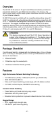
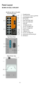
Panel Layout IE-SW-VL16(T)-16TX 1. 2. 3. 4. 5. 6. 7. 8. 9. 10. 11. 12. 13.
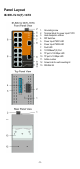
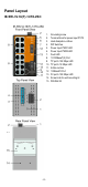
Panel Layout IE-SW-VL16(T)-14TX-2SC 1. 2. 3. 4. 5. 6. 7. 8. 9. 10. 11. 12. 13. 14. 15.
Panel Layout IE-SW-VL16(T)-14TX-2ST 1. 2. 3. 4. 5. 6. 7. 8. 9. 10. 11. 12. 13. 14. 15.
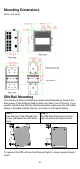
Mounting Dimensions Units: mm (inch) DIN-Rail Mounting The aluminum DIN-rail attachment plate should already be fixed to the back panel of the Ethernet Switch when you take it out of the box. If you need to reattach the DIN-rail attachment plate, make sure the stiff metal spring is situated towards the top, as shown in the figures below. STEP 1: STEP 2: Insert the top of the DIN-Rail into The DIN-Rail attachment unit will the slot just below the stiff metal snap into place as shown below. spring.
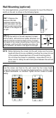
Wall Mounting (optional) For some applications, you will find it convenient to mount the Ethernet switch on the wall, as shown in the following figures. STEP 1: Remove the aluminum DIN-Rail attachment plate from the switch rear panel, and then attach the wall mount plates as shown in the diagram at the right. STEP 2: 6.0 mm Mounting the switch on the wall requires 4 screws. Use the switch, with wall mount plates attached, as a guide to mark the correct locations of the 4 screws.
ATEX Information Certificate number DEMKO 11 ATEX 150194X Ambient range: -40°C ≤ Tamb ≤ +75°C for models with suffix of “-T”; 0°C ≤ Tamb ≤ +60°C for models without suffix of “-T” Certification string: Ex nA nC IIC T4 Gc Rated Cable Temperature: ≧ 100°C Standards covered: EN 60079-0:2012+A11:2013, EN 60079-15:2010 The conditions of safe usage: These devices are to be installed in an ATEX certified IP54 enclosure accessible only with use of a tool and used in an area of not more than pollution degree 2 as de
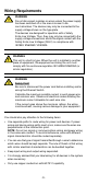
Wiring Requirements WARNING Do not disconnect modules or wires unless the power supply has been switched off or the area is known to be non-hazardous. The devices may only be connected to the supply voltage shown on the type plate. The devices are designed for operation with a Safety Extra-Low Voltage. Thus, they may only be connected to the supply voltage connections and to the signal contact with the Safety Extra-Low Voltages (SELV) in compliance with IEC950/ EN60950/ VDE0805.
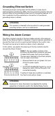
Grounding Ethernet Switch Grounding and wire routing help limit the effects of noise due to electromagnetic interference (EMI). Run the ground connection from the ground screw to the grounding surface prior to connecting devices. A 4 mm² conductor must be used when a connection to the external grounding screw is utilized. ATTENTION This product is intended to be mounted to a well-grounded mounting surface, such as a metal panel.
Wiring the Redundant Power Inputs Both power inputs can be connected simultaneously to live DC power sources. If one power source fails, the other live source acts as a backup, and automatically supplies the Ethernet Switch’s power needs. The top two contacts and the bottom two contacts of the 6-contact terminal block connector on the Ethernet Switch’s top panel are used for the Ethernet Switch’s two DC inputs. Top and front views of the terminal block connector are shown here.
Communication Connections The models of IE-SW-VL16 series have 14 or 16 10/100BaseT(X) Ethernet ports, and 2 or 0 (zero) 100 BaseFX multimode (SC/ST-type connector) fiber ports. 10/100BaseT(X) Ethernet Port Connection The 10/100BaseT(X) ports located on Ethernet Switch’s front panel are used to connect to Ethernet-enabled devices. Below we show pinouts for both MDI (NIC-type) ports and MDI-X (HUB/Switch-type) ports, and also show cable wiring diagrams for straight-through and cross-over Ethernet cables.
100BaseFX Ethernet Port Connection (Fiber) Remember to connect the Tx (transmit) port of device 1 to the Rx (receive) port of device 2, and the Rx (receive) port of device 1 to the Tx (transmit) port of device 2. Fiber optic connections generally are using the full-duplex transmission mode. SC-Port Pinouts SC-Port to SC-Port Cable Wiring ST-Port Pinouts ST-Port to ST-Port Cable Wiring ATTENTION This is a Class 1 Laser/LED product.
LED Indicators The front panel of the Ethernet Switch contains several LED indicators. The function of each LED is described in the table below. LED Color State Description Power is being supplied to power input On PWR1. PWR1 AMBER Power is not being supplied to power input Off PWR1. Power is being supplied to power input On PWR2. PWR2 AMBER Power is not being supplied to power input Off PWR2. When the corresponding PORT alarm is On enabled, and the port’s link is inactive.
Auto-Negotiation and Transmission Mode Besides the transmission speed, each RJ45 port auto-negotiates the transmission mode (half duplex or full duplex). Typically, if both devices are set to “auto-negotiation”, the full duplex transmission will be set.
Specifications Technology Standards IEEE 802.3 for 10BaseT, IEEE 802.3u for 100BaseT(X) and 100Base FX, IEEE 802.3x for Flow Control Forward and Filtering 148,810 pps (100Mbit), 14,881 pps (10Mbit) Rate Packet Buffer Memory 1.25 Mbit Store and Forward, with IEEE802.
Environmental Operating Temperature 0 to 60°C (32 to 140°F) -40 to 75°C (-40 to 167°F) for -T models -40 to 85°C (-40 to 185°F) Storage Temperature Ambient Relative 5 to 95% (non-condensing) Humidity Regulatory Approvals Safety UL 508, UL 60950-1, EN 60950-1 UL/cUL Class I, Division 2, Groups A, B, C, and D; Hazardous Location ATEX Zone 2, Ex nA nC IIC T4 Gc Maritime DNV/GL EMI FCC Part 15, CISPR (EN 55032) class A IEC 61000-4-2 ESD: Contact: 6 kV; Air: 8 kV IEC 61000-4-3 RS: 80 MHz to 1 GHz: 20 V/m IEC 6