
User Documentation

- 10 -
Grounding Ethernet Switch
Grounding and wire routing help limit the effects of noise due to
electromagnetic interference (EMI). Run the ground connection from the
ground screw to the grounding surface prior to connecting devices. A 4
mm² conductor must be used when a connection to the external
grounding screw is utilized.
ATTENTION
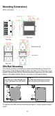
This product is intended to be mounted to a well-grounded
mounting surface, such as a metal panel.
Wiring the Alarm Contact
The Alarm Contact consists of the two middle contacts of the terminal
block on the Ethernet Switch´s top panel. A typical scenario would be to
connect the Fault circuit to a warning light located in the control room.
The light can be set up to switch on when a fault is detected.
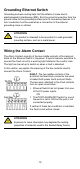
In this section, we explain the meaning of the two contacts used to
connect the Alarm Contact.
FAULT: The two middle contacts of the
6-contact terminal block connector are used
to detect both power faults and port faults.
The two wires attached to the Fault contacts
form an open circuit when:
1. Ethernet Switch has lost power from one
of the DC power inputs.
OR
2. The PORT ALARM DIP Switch for one of
the ports is set to ON, but the port is not
connected properly.
If neither of these two conditions is satisfied,
the Fault circuit will be closed.
ATTENTION
Exposure to some chemicals may degrade the sealing
properties of materials used in the Sealed Relay Device