
User Documentation

- 4 -
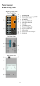
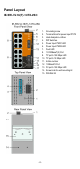
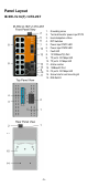
Panel Layout
IE-SW-VL16(T)-14TX-2SC
1. Grounding screw
2. Terminal block for power input P1/P2
3. Heat dissipation orifices
4. DIP Switches
5. Power input PWR1 LED
6. Power input PWR2 LED
7. Fault LED
8. 10/100BaseT(X) Port
9. TP port’s 100 Mbps LED
10. TP port’s 10 Mbps LED
11. Article number
12. 100BaseFX Port
13. FX port’s 100 Mbps LED
14. Screw hole for wall mounting kit
15. DIN-Rail Kit