
User Documentation

A1 / A2
B1 / A2
15 / 18
LED U/T
T
A
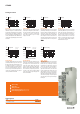
On-delay
B
A1 / A2
Pulse emitter
B1 / A2
15 / 18
LED U/T
TTT T
A1 / A2
B1 / A2
15 / 18
LED U/T
T <T
D
Off delay
A1 / A2
B1 / A2
15 / 18
LED U/T
T T
C
Passing make
1
Time setting
2
Timescale
3
Timing function
4
Status display (green): Supply voltage
5
Status display (yellow): Relays closed
IT-TIMER
Type Order-No.
ITS 24-240VUC 1CO M7C 2496190000
Ordering data
1
2
35
4
On-delay (A)
With connecting the supply voltage A1/A2, the
setted time T begins to run. At the end of time T
the output relay 15/18 switches on. This condition
remains until the supply voltage is switched off.
If the supply voltage is turned off before the end
of time T, the elapsed time will be deleted and by
connecting the supply voltage again, the time T will
be restarted.
Pulse emitter (B)
With connecting the supply voltage A1/A2 the
output relay 15/18 begans the pulse emitter. In
this case, it switches the output with the pulse-
/ pause-ratio of 1:1 (time T). The output relay
15/18 will be clocked as long as the supply
voltage is connected.
Passing make (C)
The supply voltage A1/A2 has to be connected
permernantly. Controlling the control input B1/
A2 does no effect to the output relay 15/18. By
removing the control input signal B1/A2, the
output relay15/18 will switch on and the setted
time T begans to run. At the end of time T the
output relay 15/18 switches off. A further cycle
can be started only when the current cycle has
Off delay (D)
The supply voltage A1/A2 has to be connected
permernantly. When turning on the control input
B1/A2, the output relay 15/18 switches on. If
the control signalis removed, the setted time T
begans to run. At the end of time T the output
relay 15/18 switches off. If the control input
B1/A2 is connected again before end of time
T, the current time will be deleted and will be
restarted with the next cycle.
Passing make (E)
The supply voltage A1/A2 has to be connected
permernantly. When turning on the control input
B1/A2, the output relay 15/18 switches on and
the setted time T begans to run. At the end of
time T the output relay 15/18 switches off even
when the control signal B1/A2 is still connec-
ted. A new cycle can be started only when the
current cycle is completed and a rising edge on
control input B1/A2 was detected.
Passing make (E2)
With connecting the
supply voltage A1/A2, the
output relay 15/18 switches on and the setted
time T begins to run. At the end of time T the
output relay 15/18 switches off. This state
remains until the supply voltage switched off.
When the supply voltage is switched off before
the end of time T, the output relay 15/18 swit-
ches off, too. The current time will be deleted
and by connecting the supply voltage again the
time T will be restared.
The supply voltage A1/A2 has to be connected
permernantly. By connecting a control signal at
B1/A2 (<0,8 s) the output relay 15/18 will
be switched on for setted time T. At the end
of time T the output relay 15/18 will fell off.
If the control signal at 15/18 is switched on
again befor the end of time T, the current time
T will be canceled and the output relay 15/18
switched off. By connecting a control signal at
B1/A2 (>0,8 s) the output relay 15/18 will be
switched on permanantly. After permanant acit-
vation of the output relay 15/18, the relay will
only swtich off by connecting the control signal
B1/A2 again.
Timing functions
A1 / A2
B1 / A2
15 / 18
LED U/T
E
Passing make
T T
rising edge with
control input
A1 / A2
B1 / A2
15 / 18
LED U/T
T <T
E2
Passing make
Function E with jumper between A1-B1
rising edge supply
voltage controlled
A1 / A2
B1 / A2
15 / 18
LED U/T
T <T
< 0,8s
T = ∞
F
Flip-flop / latching