
Brochure/Catalogue


Klippon
®
KUB Cable Glands
Structure of the part description
Order key [Type] [a] [b] [c] [d] [e] [f] [ggg]
Example article description KUB M20 B S O SC 1 G16
Meaning [Type] = Gland type (KUB)
[a] = Entry thread (M20-M75)
[b] = Material (B = brass)
[c] = Seal material (S = Silicone)
[d] = Continuity for lead sheath (L = yes, O = no)
[e] = Plating (SC = self-coloured, NI = Nickel)
[f] = Cable outer sheath (1 = Reduced, 2 = Standard)
[ggg] = Gland size (G16-G75)
A
D
C
B
Note Refer to page D.22 Selection Guide Klippon
®
Cable Glands to determine the suitable order number
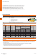
Dimensions
Gland Seal Range
Gland Size Entry
thread
Entry
thread
Length
Max
Outer
Diameter
Max
Length
Cable
Inner Sheath
[C]
Cable
Outer Sheath
[D]
Armour
Acceptance
Range
Shroud
Size
Standard
[f] = 2
Reduced
[f] = 1[ggg] [a] [B] [A]
X Y Z Min Max Min Max
G16 M20 16 28.0 72.0 7 9.0 11.7 9.0 13.5 6.7 10.3 0.15 - 1.25 L24
G20S M20 16 28.0 72.0 8 10.4 11.7 11.5 16.0 9.4 12.5 0.15 - 1.25 L24
G20 M20 16 33.0 73.0 14 12.5 14.0 15.5 21.1 12.0 17.6 0.15 - 1.25 EL30
G25 M25 16 41.4 83.0 25 17.8 20.0 20.3 27.4 16.8 23.9 0.15 - 1.60 EL38
G32 M32 16 50.6 103.0 50 23.5 26.3 26.7 34.0 23.2 30.5 0.15 - 2.00 EL46
G40 M40 16 60.5 105.0 80 28.8 32.2 33.0 40.6 28.6 36.2 0.20 - 2.00 EL55
G50S M50 16 71.5 115.0 100 34.2 38.2 39.4 46.7 34.8 42.4 0.30 - 2.50 EL65
G50 M50 16 71.5 115.0 100 39.4 44.1 45.7 53.2 41.1 48.5 0.30 - 2.50 EL65
G63S M63 19 88.0 115.0 120 44.8 50.1 52.1 59.5 47.5 54.8 0.30 - 2.50 EL80
G63 M63 19 88.0 115.0 120 50.0 56.0 58.4 65.8 53.8 61.2 0.30 - 2.50 EL80
G75S M75 19 99.0 122.0 140 55.4 62.0 64.8 72.2 60.2 68.0 0.30 - 2.50 EL90
G75 M75 19 99.0 122.0 140 60.8 68.0 71.1 78.0 66.5 73.4 0.30 - 2.50 EL90
Dimensions in mm
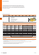
Important Notes
• The gland size does not necessarily equate to the entry thread size.
• In some cases several gland sizes can be chosen due to overlapping inner as well as outer cable diameters. Due to the wide range of armoured cables available, it is necessary to select the correct clamping range.
This is achieved by taking the inner and outer clamping range values to determine the best t (as close as possible to the Min/Max values average).
• X = Maximum numbers of cores
• Y = Maximum over cores
• Z = Maximum inner sheath
• All cable glands have a 1.5 mm pitch.
• For Flameproof Ex d applications the female thread into which the gland is to be tted must achieve an engagement of at least 5 full threads in compliance with clause 5.3 of EN/IEC 60079-1.
• Where KUB glands are tted into non-metallic Increased Safety Ex e enclosures they must be included within the earth circuit of the system
• Fully assembly instructions are supplied with the glands. The instructions must be read prior to installation and adhered to in full.
• When the gland is used to terminate un-armoured cables, the gland is suitable only for xed installation.
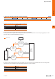
The KUB gland provide an armour clamp for steel tape, steel wire and braided cables. An electrical bond
between the cable armour and the gland is ensured. The gland can also be used to terminate unarmoured
cables. Additionally, the gland provides a single pull resistant seal on the outer sheath of any cable. After
clamping the cable armour onto the cone, the cable has to be lled with the provided compound to seal the
free spaces between the single conductors.
The gland maintains a temperature range from -60 °C to +135 °C. When lled, the gland fullls an IP
rating of IP68 to 100 metres (30 Min. at 10 bar). The KUB gland is only suitable for pressure-resistant Ex d
encapsulation, and is available on request.
D
D.212712630000
Cable entries