
Approval/Certificate/Document of Conformity


SCHEDULE
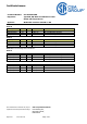
EU-TYPE EXAMINATION CERTIFICATE Sira 05ATEX1288X
Issue 5
This certificate and its schedules may only be
reproduced in its entirety and without change
CSA Group Netherlands B.V.
Utrechseweg 310,
6812 AR, Arnhem Netherlands
DQD 544.11 Rev 2018-04-20 Page 5 of 9
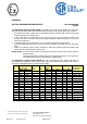
The KUB Range of Barrier Cable Glands are suitable for use with circular, pliable wire, single wire
and steel tape armoured cables along with braided/screened and unarmoured cables; they comprise:
a threaded entry body to tighten into an associated enclosure, this fitted with a silicone O-ring and
internally coated with a release agent
a cone, fitted with an external nitrile O-ring, which fits into the entry component to make a part
chamber into which a two part epoxy putty setting compound is applied to provide an inner seal
around the conductors.
a clamp ring that secures cable armour to the cone and also provides earth protection
a mid-cap component that fastens to the entry body to captivate the clamp ring, cone and epoxy
putty
a back nut, enclosing a white, silicone, elastomeric, cable outer sheath seal and skid washer, that
screws onto the external thread of the mid cap.
Design option: A brass continuity washer may be fitted in the 20S to 100 sizes for use with lead inner
sheathed cables.
The KUB size 20s and 20 cable glands to be used with an alternative, cone component;
(see details below) and are only suitable for braided cables:
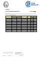
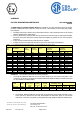
The KUB Range of Barrier Cable Glands also has a reduced bore outer sheath seal option to
accommodate an alternative range of outer sheath cable sizes. Reduced bore seals are red in colour.
This option is designated with a ‘1’ in the full part number.
Gland
Size
Standard
Entry threads
Max Ø
over
cores
Max No
of
Cores
Inner
Sheath
Outer Sheath
Reduced Bore
Armour
Dia./Thickness
(Universal)
Metric
NPT
Max
Min
Max
Min
Max
16
M20
½” NPT
10.4
15
11.7
8.4
13.5
6.7
10.3
0.15 - 1.25
20S
M20
½” NPT
10.4
35
11.7
11.5
16.0
9.4
12.5
*0.15 - 1.25
20
M20
½” NPT
12.5
40
14.0
15.5
21.1
12.0
17.6
**0.15 - 1.25
25
M25
¾” NPT
17.8
60
20.0
20.3
27.4
16.8
23.9
0.15 - 1.6
32
M32
1” NPT
23.5
80
26.3
26.7
34.0
23.2
30.5
0.15 - 2.0
40
M40
1 ¼” NPT
28.8
130
32.2
33.0
40.6
28.6
36.2
0.2 - 2.0
50S
M50
1 ½” NPT
34.2
200
38.2
39.4
46.7
34.8
42.4
0.2 - 2.5
50
M50
2” NPT
39.4
400
44.1
45.7
53.2
41.1
48.5
0.2 - 2.5
63S
M63
2” NPT
44.8
400
50.1
52.1
59.5
47.5
54.8
0.3 - 2.5
63
M63
2 ½” NPT
50.0
425
56.0
58.4
65.8
53.8
61.2
0.3 - 2.5
75S
M75
2 ½” NPT
55.4
425
62.0
64.8
72.2
60.2
68.0
0.3 - 2.5
75
M75
3” NPT
60.8
425
68.0
71.1
78.0
66.5
73.4
0.3 - 2.5
80
M80
3” NPT
64.4
425
72.0
77.0
84.0
71.9
79.4
0.45 - 3.15
85
M85
3” NPT
69.8
425
78.0
79.6
90.0
75.0
85.4
0.45 - 3.15
90
M90
3 ½” NPT
75.1
425
84.0
88.0
96.0
82.0
91.4
0.45 - 3.15
100
M100
3 ½” NPT
80.5
425
90.0
92.0
102.0
87.4
97.4
0.45 - 3.15