
User Documentation

Instructions for safe use
2493040000/00/09.168
9. Check compound has not passed its “Use By” date.
Installation at temperatures below 10° C should be
avoided. Trim any hardened pieces from ends of stick
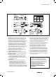
10. Mix the compound by rolling, folding and breaking.
Ease mixing by cutting large sticks in half. Fully mixed
compound has a uniform yellow colour with no streaks
See Figure 1 for correctly mixed compound.
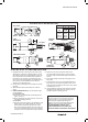
11. Support the cable and rear gland assembly. With
unarmoured cable, hold Cone and cable roughly
concentric. Splay out the cores. Starting at the middle,
pack small amounts of rolled-out compound between
the cores. Re-straighten each core and work outwards
until all gaps are filled. Bundle the cores with cord or
tape (see Figure 2) so they are not disturbed. Pack
around the outside of the outer cores to fill the Cone
cup. Build up compound around the outside of the
cores with a slight taper and to approximate compound
length shown in diagram and Table 1 column 11.
12. Pass cores through & push compound into Entry Body
until Cone engages. Remove squeezed out compound
at arrow B. For thickest armour: Screw Mid Cap 7 full
turns onto Entry Body (arrow C). For tape armours/
braids: screw no further than groove (sizes 16 & 20S:
screw no further than 6mm [1/4 inch] from Entry Body
hexagon) (arrow D). Ensure that compound emerges at
entry thread (arrow E).
13. Clean off excess compound from Entry Body to allow
withdrawal when cured (arrow E). Cores may be
disturbed after 1 hour. Leave to cure for 4 hours when
working at 21º C.
14. To release the joint for inspection unscrew the Mid Cap.
Using a wrench on the Cone, rotate the cone no more
than 1/16 of a turn. This will release the compound from
the entry body. Do not over rotate as this may damage
cable braid. Pull the cone and compound out for
inspection. The compound should appear as in Figure
3 with no gaps, holes or cracks.
15. Hand-tighten Mid Cap to remake joint. Then refer to
table below and tighten using wrench to the given
amount.
16. Hold Mid Cap with wrench and tighten Back Nut onto
cable. Ensure seal makes full contact with cable
sheath, and then tighten Back Nut 1 extra turn.
17. The equipment should not be energised until the
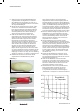
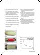
compound has been left to cure for at least 4 hours
when working at 21º C. See chart ‘Energising Time vs.
Temperature’ for further guidance
INSTRUCTIONS FOR SAFE USE
Issue: 5 W eidmüller Interface GmbH & Co. KG
Date: 29/04/2013 Klingenbergstrasse 16, 32758 Detmold, Germany
Doc: WA111 Page: 2 of 2
turns onto Entry Body (arrow C). For tape armours/braids: screw no further than groove (sizes 16 & 20S: screw no further than 6mm [1/4 inch] from Entry Body
hexagon) (arrow D). Ensure that compound emerges at entry thread (arrow E).
13 Clean off excess compound from Entry Body to allow withdrawal when cured (arrow E). Cores may be disturbed after 1 hour. Leave to cure for 4 hours when working
at 21º C.
14 To release the joint for inspection unscrew the Mid Cap. Using a wrench on the Cone, rotate the cone no more than 1/16 of a turn. This will release the compound
from the entry body. Do not over rotate as this may damage cable braid. Pull the cone and compound out for inspection. The compound should appear as in Figure
3 with no gaps, holes or cracks.
15 Hand-tighten Mid Cap to remake joint. Then refer to table below and tighten using wrench to the given amount.
16 Hold Mid Cap with wrench and tighten Back Nut onto cable. Ensure seal makes full contact with cable sheath, and then tighten Back Nut 1 extra turn.
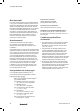
17 The equipment should not be energised until the compound has been left to cure for at least 4 hours when working at 21º C. See chart ‘Energising Time vs.
Temperature’ for further guidance
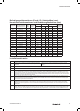
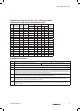
Tightening information (Point 15), cable sizes (mm), construction and armour acceptance (mm)
Installation Guidance
Point Advice
1
♦ EN/IEC 60079-10 Classification of Hazardous Areas
♦ EN/IEC 60079-14 Electrical Installations in Hazardous Areas
♦ EN/IEC 60079-31 Ignitable dust – Protection by enclosure
♦ BS 6121, Part 5 Selection, Installation & Maintenance of Cable Glands
2 Installation should only be carried out by a competent electrician, skilled in cable gland installation.
3 NO INSTALLATION SHOULD BE CARRIED OUT UNDER LIVE CONDITIONS.
4
Threaded entries: the product can be installed directly into threaded entries. Threaded entries should comply with clause 5.3 of IEC/EN 60079-1 and have
a lead-in chamfer to allow for full engagement of the threads. For Ex d applications a minimum of 5 fully engaged parallel threads is required. Metric
threads are supplied with an o-ring and will maintain IP66 and IP68. Parallel entry threads will maintain an IP rating of IP64. A sealing washer should be
used to maintain all IP ratings greater than IP64.
5
To maintain the Ingress Protection rating of the product, the entry hole must be perpendicular to the surface of the enclosure. The surface should be
sufficiently flat and rigid to make the IP joint. The surface must be clean and dry. It is the users/installers responsibility to ensure that the interface
between the enclosure and cable gland is suitably sealed for the required application.
6
Whilst Weidmuller products with tapered threads, when installed into a threaded entry, have been tested to maintain IP66 without any additional sealant,
due to the differing gauging tolerances associated with the use of tapered threads it is recommended to use a non-hardening thread sealant if an IP rating
higher than IP64 is required.
7
Once installed do not dismantle except for routine inspection. An inspection should be conducted as per IEC/EN 60079-17. After inspection the gland
should be re-assembled as detailed in points 15 and 16, ensuring the Mid Cap and back nut are correctly tightened to ensure the installation is secure.
Interpretation of Markings. Markings on the outside of this gland carry the following meanings:
KUB [a] [b] [c] [d] [e] [f] [ggg]
W here: [a] = Entry thread
[b] = Main component material (B = brass, S = stainless steel)
[c] = Seal material (S = silicone, N = Neoprene)
[d] = Continuity for lead sheath (L = yes, O = no)
[e] = Plating (Sc = self coloured, Ni = Nickel, Zi = zinc)
[f] = Reduced bore outer seal (1 = yes, 2 = no)
[ggg] = Gland size (Gsss) (e.g. G20S)
Certificate Numbers (ATEX) SIRA 05ATEX1288X (IECEx) IECEx SIR 05.0067X
Protection Concept, EPL’s and Gas Groups: Ex d I&IIC Exe I&IIC Mb Gb / Ex ta IIIC Da
Environmental Protection: IP66 / IP68 (100 metres for 7 Days)
ATEX (EU Directive 94/9/EC) Markings: I M2 II 1D II 2G
Special Conditions for Safe Use
1. The cable glands shall not be used in enclosures where the temperature, at the point of mounting, is outside the range of -60° C to +135° C.
2. The entry component threads will be suitably sealed using a method that is applicable to the associated equipment to which the gland will be
attached. This will be in accordance with the relevant installation code of practice and will ensure that any ingress protection and restricted breathing
sealing requirements are maintained.
3. When glands without sealing rings are installed in an explosive dust atmosphere, they shall only be fitted into enclosures that have entries that will
ensure that a minimum of 5 full threads of contact will be maintained, this is in accordance with clause 5.1.1 of EN 60079-31:2009.
Inner
Sheath
Outer Sheath Reduced
Bore
Gland
Size
Tighten Mid
Cap using
wrench up to
Max Ø
over
cores
Max
No of
Cores
Max Min Max Min Max
Armour
size
Universal
16 ½-turn 9.0 15 11.7 8.4 13.5 6.7 10.3 0.1 -1.25
20S ½-turn 10.4 35 11.7 11.5 16.0 9.4 12.5 0.1 -1.25
20 ½-turn 12.5 40 14.0 15.5 21.1 12.0 17.6 0.1 -1.25
25 ½-turn 17.8 60 20.0 20.3 27.4 16.8 23.9 0.1 -1.6
32 ½-turn 23.5 80 26.3 26.7 34.0 23.2 30.5 0.1 -2.0
40 ½-turn 28.8 130 32.2 33.0 40.6 28.6 36.2 0.1 -2.0
50S ½-turn 34.2 200 38.2 39.4 46.7 34.8 42.4 0.1 -2.5
50 ½-turn 39.4 400 44.1 45.7 53.2 41.1 48.5 0.1 -2.5
63S ½-turn 44.8 400 50.1 52.1 59.5 47.5 54.8 0.1 -2.5
63 ½-turn 50.0 425 56.0 58.4 65.8 53.8 61.2 0.1 -2.5
75S ½-turn 55.4 425 62.0 64.8 72.2 60.2 68.0 0.1 -2.5
75 ½-turn 60.8 425 68.0 71.1 78.0 66.5 73.4 0.1 -2.5
80 ¾-turn 64.4 425 72.0 77.0 84.0 71.9 79.4 0.1 -3.15
85 ¾-turn 69.8 425 78.0 79.6 90.0 75.0 85.4 0.1 -3.15
90 ¾-turn 75.1 425 84.0 88.0 96.0 82.0 91.4 0.1 -3.15
100 ¾-turn 80.5 425 90.0 92.0 102.0 87.4 97.4 0.1 -3.15
Figure 1
Figure 3
Figure 2
Figure 1
INSTRUCTIONS FOR SAFE USE
Issue: 5 W eidmüller Interface GmbH & Co. KG
Date: 29/04/2013 Klingenbergstrasse 16, 32758 Detmold, Germany
Doc: WA111 Page: 2 of 2
turns onto Entry Body (arrow C). For tape armours/braids: screw no further than groove (sizes 16 & 20S: screw no further than 6mm [1/4 inch] from Entry Body
hexagon) (arrow D). Ensure that compound emerges at entry thread (arrow E).
13 Clean off excess compound from Entry Body to allow withdrawal when cured (arrow E). Cores may be disturbed after 1 hour. Leave to cure for 4 hours when working
at 21º C.
14 To release the joint for inspection unscrew the Mid Cap. Using a wrench on the Cone, rotate the cone no more than 1/16 of a turn. This will release the compound
from the entry body. Do not over rotate as this may damage cable braid. Pull the cone and compound out for inspection. The compound should appear as in Figure
3 with no gaps, holes or cracks.
15 Hand-tighten Mid Cap to remake joint. Then refer to table below and tighten using wrench to the given amount.
16 Hold Mid Cap with wrench and tighten Back Nut onto cable. Ensure seal makes full contact with cable sheath, and then tighten Back Nut 1 extra turn.
17 The equipment should not be energised until the compound has been left to cure for at least 4 hours when working at 21º C. See chart ‘Energising Time vs.
Temperature’ for further guidance
Tightening information (Point 15), cable sizes (mm), construction and armour acceptance (mm)
Installation Guidance
Point Advice
1
♦ EN/IEC 60079-10 Classification of Hazardous Areas
♦ EN/IEC 60079-14 Electrical Installations in Hazardous Areas
♦ EN/IEC 60079-31 Ignitable dust – Protection by enclosure
♦ BS 6121, Part 5 Selection, Installation & Maintenance of Cable Glands
2 Installation should only be carried out by a competent electrician, skilled in cable gland installation.
3 NO INSTALLATION SHOULD BE CARRIED OUT UNDER LIVE CONDITIONS.
4
Threaded entries: the product can be installed directly into threaded entries. Threaded entries should comply with clause 5.3 of IEC/EN 60079-1 and have
a lead-in chamfer to allow for full engagement of the threads. For Ex d applications a minimum of 5 fully engaged parallel threads is required. Metric
threads are supplied with an o-ring and will maintain IP66 and IP68. Parallel entry threads will maintain an IP rating of IP64. A sealing washer should be
used to maintain all IP ratings greater than IP64.
5
To maintain the Ingress Protection rating of the product, the entry hole must be perpendicular to the surface of the enclosure. The surface should be
sufficiently flat and rigid to make the IP joint. The surface must be clean and dry. It is the users/installers responsibility to ensure that the interface
between the enclosure and cable gland is suitably sealed for the required application.
6
Whilst Weidmuller products with tapered threads, when installed into a threaded entry, have been tested to maintain IP66 without any additional sealant,
due to the differing gauging tolerances associated with the use of tapered threads it is recommended to use a non-hardening thread sealant if an IP rating
higher than IP64 is required.
7
Once installed do not dismantle except for routine inspection. An inspection should be conducted as per IEC/EN 60079-17. After inspection the gland
should be re-assembled as detailed in points 15 and 16, ensuring the Mid Cap and back nut are correctly tightened to ensure the installation is secure.
Interpretation of Markings. Markings on the outside of this gland carry the following meanings:
KUB [a] [b] [c] [d] [e] [f] [ggg]
W here: [a] = Entry thread
[b] = Main component material (B = brass, S = stainless steel)
[c] = Seal material (S = silicone, N = Neoprene)
[d] = Continuity for lead sheath (L = yes, O = no)
[e] = Plating (Sc = self coloured, Ni = Nickel, Zi = zinc)
[f] = Reduced bore outer seal (1 = yes, 2 = no)
[ggg] = Gland size (Gsss) (e.g. G20S)
Certificate Numbers (ATEX) SIRA 05ATEX1288X (IECEx) IECEx SIR 05.0067X
Protection Concept, EPL’s and Gas Groups: Ex d I&IIC Exe I&IIC Mb Gb / Ex ta IIIC Da
Environmental Protection: IP66 / IP68 (100 metres for 7 Days)
ATEX (EU Directive 94/9/EC) Markings: I M2 II 1D II 2G
Special Conditions for Safe Use
1. The cable glands shall not be used in enclosures where the temperature, at the point of mounting, is outside the range of -60° C to +135° C.
2. The entry component threads will be suitably sealed using a method that is applicable to the associated equipment to which the gland will be
attached. This will be in accordance with the relevant installation code of practice and will ensure that any ingress protection and restricted breathing
sealing requirements are maintained.
3. When glands without sealing rings are installed in an explosive dust atmosphere, they shall only be fitted into enclosures that have entries that will
ensure that a minimum of 5 full threads of contact will be maintained, this is in accordance with clause 5.1.1 of EN 60079-31:2009.
Inner
Sheath
Outer Sheath Reduced
Bore
Gland
Size
Tighten Mid
Cap using
wrench up to
Max Ø
over
cores
Max
No of
Cores
Max Min Max Min Max
Armour
size
Universal
16 ½-turn 9.0 15 11.7 8.4 13.5 6.7 10.3 0.1 -1.25
20S ½-turn 10.4 35 11.7 11.5 16.0 9.4 12.5 0.1 -1.25
20 ½-turn 12.5 40 14.0 15.5 21.1 12.0 17.6 0.1 -1.25
25 ½-turn 17.8 60 20.0 20.3 27.4 16.8 23.9 0.1 -1.6
32 ½-turn 23.5 80 26.3 26.7 34.0 23.2 30.5 0.1 -2.0
40 ½-turn 28.8 130 32.2 33.0 40.6 28.6 36.2 0.1 -2.0
50S ½-turn 34.2 200 38.2 39.4 46.7 34.8 42.4 0.1 -2.5
50 ½-turn 39.4 400 44.1 45.7 53.2 41.1 48.5 0.1 -2.5
63S ½-turn 44.8 400 50.1 52.1 59.5 47.5 54.8 0.1 -2.5
63 ½-turn 50.0 425 56.0 58.4 65.8 53.8 61.2 0.1 -2.5
75S ½-turn 55.4 425 62.0 64.8 72.2 60.2 68.0 0.1 -2.5
75 ½-turn 60.8 425 68.0 71.1 78.0 66.5 73.4 0.1 -2.5
80 ¾-turn 64.4 425 72.0 77.0 84.0 71.9 79.4 0.1 -3.15
85 ¾-turn 69.8 425 78.0 79.6 90.0 75.0 85.4 0.1 -3.15
90 ¾-turn 75.1 425 84.0 88.0 96.0 82.0 91.4 0.1 -3.15
100 ¾-turn 80.5 425 90.0 92.0 102.0 87.4 97.4 0.1 -3.15
Figure 1
Figure 3
Figure 2
Figure 2
INSTRUCTIONS FOR SAFE USE
Issue: 5 W eidmüller Interface GmbH & Co. KG
Date: 29/04/2013 Klingenbergstrasse 16, 32758 Detmold, Germany
Doc: WA111 Page: 2 of 2
turns onto Entry Body (arrow C). For tape armours/braids: screw no further than groove (sizes 16 & 20S: screw no further than 6mm [1/4 inch] from Entry Body
hexagon) (arrow D). Ensure that compound emerges at entry thread (arrow E).
13 Clean off excess compound from Entry Body to allow withdrawal when cured (arrow E). Cores may be disturbed after 1 hour. Leave to cure for 4 hours when working
at 21º C.
14 To release the joint for inspection unscrew the Mid Cap. Using a wrench on the Cone, rotate the cone no more than 1/16 of a turn. This will release the compound
from the entry body. Do not over rotate as this may damage cable braid. Pull the cone and compound out for inspection. The compound should appear as in Figure
3 with no gaps, holes or cracks.
15 Hand-tighten Mid Cap to remake joint. Then refer to table below and tighten using wrench to the given amount.
16 Hold Mid Cap with wrench and tighten Back Nut onto cable. Ensure seal makes full contact with cable sheath, and then tighten Back Nut 1 extra turn.
17 The equipment should not be energised until the compound has been left to cure for at least 4 hours when working at 21º C. See chart ‘Energising Time vs.
Temperature’ for further guidance
Tightening information (Point 15), cable sizes (mm), construction and armour acceptance (mm)
Installation Guidance
Point Advice
1
♦ EN/IEC 60079-10 Classification of Hazardous Areas
♦ EN/IEC 60079-14 Electrical Installations in Hazardous Areas
♦ EN/IEC 60079-31 Ignitable dust – Protection by enclosure
♦ BS 6121, Part 5 Selection, Installation & Maintenance of Cable Glands
2 Installation should only be carried out by a competent electrician, skilled in cable gland installation.
3 NO INSTALLATION SHOULD BE CARRIED OUT UNDER LIVE CONDITIONS.
4
Threaded entries: the product can be installed directly into threaded entries. Threaded entries should comply with clause 5.3 of IEC/EN 60079-1 and have
a lead-in chamfer to allow for full engagement of the threads. For Ex d applications a minimum of 5 fully engaged parallel threads is required. Metric
threads are supplied with an o-ring and will maintain IP66 and IP68. Parallel entry threads will maintain an IP rating of IP64. A sealing washer should be
used to maintain all IP ratings greater than IP64.
5
To maintain the Ingress Protection rating of the product, the entry hole must be perpendicular to the surface of the enclosure. The surface should be
sufficiently flat and rigid to make the IP joint. The surface must be clean and dry. It is the users/installers responsibility to ensure that the interface
between the enclosure and cable gland is suitably sealed for the required application.
6
Whilst Weidmuller products with tapered threads, when installed into a threaded entry, have been tested to maintain IP66 without any additional sealant,
due to the differing gauging tolerances associated with the use of tapered threads it is recommended to use a non-hardening thread sealant if an IP rating
higher than IP64 is required.
7
Once installed do not dismantle except for routine inspection. An inspection should be conducted as per IEC/EN 60079-17. After inspection the gland
should be re-assembled as detailed in points 15 and 16, ensuring the Mid Cap and back nut are correctly tightened to ensure the installation is secure.
Interpretation of Markings. Markings on the outside of this gland carry the following meanings:
KUB [a] [b] [c] [d] [e] [f] [ggg]
W here: [a] = Entry thread
[b] = Main component material (B = brass, S = stainless steel)
[c] = Seal material (S = silicone, N = Neoprene)
[d] = Continuity for lead sheath (L = yes, O = no)
[e] = Plating (Sc = self coloured, Ni = Nickel, Zi = zinc)
[f] = Reduced bore outer seal (1 = yes, 2 = no)
[ggg] = Gland size (Gsss) (e.g. G20S)
Certificate Numbers (ATEX) SIRA 05ATEX1288X (IECEx) IECEx SIR 05.0067X
Protection Concept, EPL’s and Gas Groups: Ex d I&IIC Exe I&IIC Mb Gb / Ex ta IIIC Da
Environmental Protection: IP66 / IP68 (100 metres for 7 Days)
ATEX (EU Directive 94/9/EC) Markings: I M2 II 1D II 2G
Special Conditions for Safe Use
1. The cable glands shall not be used in enclosures where the temperature, at the point of mounting, is outside the range of -60° C to +135° C.
2. The entry component threads will be suitably sealed using a method that is applicable to the associated equipment to which the gland will be
attached. This will be in accordance with the relevant installation code of practice and will ensure that any ingress protection and restricted breathing
sealing requirements are maintained.
3. When glands without sealing rings are installed in an explosive dust atmosphere, they shall only be fitted into enclosures that have entries that will
ensure that a minimum of 5 full threads of contact will be maintained, this is in accordance with clause 5.1.1 of EN 60079-31:2009.
Inner
Sheath
Outer Sheath Reduced
Bore
Gland
Size
Tighten Mid
Cap using
wrench up to
Max Ø
over
cores
Max
No of
Cores
Max Min Max Min Max
Armour
size
Universal
16 ½-turn 9.0 15 11.7 8.4 13.5 6.7 10.3 0.1 -1.25
20S ½-turn 10.4 35 11.7 11.5 16.0 9.4 12.5 0.1 -1.25
20 ½-turn 12.5 40 14.0 15.5 21.1 12.0 17.6 0.1 -1.25
25 ½-turn 17.8 60 20.0 20.3 27.4 16.8 23.9 0.1 -1.6
32 ½-turn 23.5 80 26.3 26.7 34.0 23.2 30.5 0.1 -2.0
40 ½-turn 28.8 130 32.2 33.0 40.6 28.6 36.2 0.1 -2.0
50S ½-turn 34.2 200 38.2 39.4 46.7 34.8 42.4 0.1 -2.5
50 ½-turn 39.4 400 44.1 45.7 53.2 41.1 48.5 0.1 -2.5
63S ½-turn 44.8 400 50.1 52.1 59.5 47.5 54.8 0.1 -2.5
63 ½-turn 50.0 425 56.0 58.4 65.8 53.8 61.2 0.1 -2.5
75S ½-turn 55.4 425 62.0 64.8 72.2 60.2 68.0 0.1 -2.5
75 ½-turn 60.8 425 68.0 71.1 78.0 66.5 73.4 0.1 -2.5
80 ¾-turn 64.4 425 72.0 77.0 84.0 71.9 79.4 0.1 -3.15
85 ¾-turn 69.8 425 78.0 79.6 90.0 75.0 85.4 0.1 -3.15
90 ¾-turn 75.1 425 84.0 88.0 96.0 82.0 91.4 0.1 -3.15
100 ¾-turn 80.5 425 90.0 92.0 102.0 87.4 97.4 0.1 -3.15
Figure 1
Figure 3
Figure 2
Figure 3
50°C
40°C
30°C
20°C
10°C
0°C
04812162024
hrs
Energising Time
vs. Temperature