Klippon ® KUB Compound – Filled Cable Gland Sicherheitshinweise............................ 2 Instructions for safe use.................... 6 Consignes de sécurité...................... 10 Instrucciones para un uso seguro.. 14 Istruzioni per un uso sicuro.............
Sicherheitshinweise Kurzbeschreibung Die KUB-Vergussverschraubung ist für Außenan wendungen im entsprechenden Gefahrenbereich vorgesehen. Die KUB-Ausführung eignet sich für den Anschluss von biegsamen Leitungen, Stahldrahtbewehrungs-, Bandeisenbewehrungs-, umflochtenen, abgeschirmten und nicht bewehrten Kabeln. Eine Variante, die elektrischen Durchgang für einen Bleimantel bietet, ist erhältlich. Sie bietet einen Schutz von IP66, IP68 und gegen Überflutung.
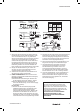
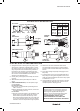
Sicherheitshinweise SCHRITT-FÜR-SCHRITT-INSTALLATIONSANWEISUNGEN ZERLEGTE VERSCHRAUBUNG Durchgangsunterlegscheibe (sofern installiert) Spannmutter Mittelstück Klemme Kegel KABELVORBEREITUNG Kabeleinführung Bleimantel TABELLE 1 4 VerschrauBewehbungsrungsgröße länge 16 – 25 20 – 22 mm 32 – 40 30 mm 50S – 75 32 mm 80 – 100 50 mm VERGUSSDICHTUNG 11 Vergusslänge 40 mm 45 mm 50 mm 60 mm Bleimantel AUSPRESSUNG VERGUSSMASSE ABGESCHLOSSENE INSTALLATION SCHRITT-FÜR-SCHRITT-INSTALLATIONSANWEISUNG 1.
Sicherheitshinweise 9. Stellen Sie sicher, dass das Haltbarkeitsdatum des Kegel eingreift. Entfernen Sie die ausgedrückte Vergussmaterials nicht abgelaufen ist. Vermeiden Vergussmasse, die durch Pfeil B angezeigt wird. Für Sie Installationen bei Temperaturen von unter 10 °C. die dickste Bewehrung: Schrauben Sie das Mittelstück Entfernen Sie die ausgehärteten Stücke von den Enden sieben vollständige Drehungen auf die Kabeleinführung der Vergussmaterialstangen. (Pfeil C).
Sicherheitshinweise Befestigungsinformationen (Punkt 15), Kabelgrößen (mm), Konstruktionsinformationen und Bewehrungsaufnahme (mm) Festdrehen des MittelVerschraustücks mit Schraubenbungsgröße schlüssel um bis zu Max. Ø über Adern Max. Innenmantel Anzahl der Max. Adern Außenmantel Min. Max. Min. Max. Bewehrungsgröße Universal Verjüngte Bohrung 16 ½-Drehung 9.0 15 11.7 8.4 13.5 6.7 10.3 0.1 -1.25 20S ½-Drehung 10.4 35 11.7 11.5 16.0 9.4 12.5 0.1 -1.25 20 ½-Drehung 12.5 40 14.
Instructions for safe use Brief Description The KUB type Compound-filled cable gland is for outdoor use in the appropriate Hazardous Areas with pliable wire/ steel wire/ steel tape armoured, braided, screened and un-armoured cable. A variant giving electrical continuity to a lead sheath is available. It gives environmental protection to IP66, IP68 and Deluge. A termination suitable for EMC protection can be made using armoured cables with this gland.
Instructions for safe use STEP-BY-STEP FITTING INSTRUCTIONS SPLIT GLAND Continuity washer (Where fitted) Gland Size Back Nut Mid Cap Clamp CABLE PREPARATION Cone 16 – 25 32 – 40 50S – 75 80 – 100 Entry Body COMPOUND PACKING Lead Sheath TABLE 1 4 Armour Length 11 Compound Length 20 – 22 mm 30 mm 32 mm 50 mm 40 mm 45 mm 50 mm 60 mm Lead Sheath COMPOUND EXTRUSION COMPLETED INSTALLATION STEP-BY-STEP FITTING INSTRUCTION 1. Split gland as shown. Warning.
Instructions for safe use 9. Check compound has not passed its “Use By” date. 13. Clean off excess compound from Entry Body to allow Installation at temperatures below 10° C should be withdrawal when cured (arrow E). Cores may be avoided. Trim any hardened pieces from ends of stick disturbed after 1 hour. Leave to cure for 4 hours when working at 21º C. 10. Mix the compound by rolling, folding and breaking. Ease mixing by cutting large sticks in half. Fully mixed 14.
Instructions for safe use Tightening information (Point 15), cable sizes (mm), construction and armour acceptance (mm) Gland Tighten Mid size Cap using wrench up to Max Ø over cores Max No of Cores Inner Sheath Max Outer Sheath Min Max Min Max Armour size Universal Reduced Bore 16 ½-turn 9.0 15 11.7 8.4 13.5 6.7 10.3 0.1 -1.25 20S ½-turn 10.4 35 11.7 11.5 16.0 9.4 12.5 0.1 -1.25 20 ½-turn 12.5 40 14.0 15.5 21.1 12.0 17.6 0.1 -1.25 25 ½-turn 17.8 60 20.0 20.
Consignes de sécurité. Bref descriptif Le presse-étoupe à masse de remplissage KUB est conçu pour une utilisation extérieure, dans une zone dangereuse adéquate avec des câbles flexibles/des câbles en acier/des câbles armés à ruban d‘acier/ des câbles tressés/des câbles blindés ou non-armés. Il existe une variante garantissant une continuité électrique à une gaine de plomb. Elle garantit une protection environnementale d‘indices de protection IP66, IP68 et Deluge.
Consignes de sécurité.
Consignes de sécurité. 9. Vérifier que le produit de remplissage n’a pas dépassé (flèche C). Pour les armatures à ruban/ tresses, ne pas la « date de péremption ». Éviter une installation à une visser au-delà de la rainure (tailles 16 et 20S : ne pas température inférieure à 10° C. Rogner toute pièce visser au-delà de 6 mm [1/4 pouce] depuis l’hexagone durcie à partir des extrémités. du corps d’entrée) (flèche D). S’assurer que le produit sorte au filetage d’entrée (flèche E). 10.
Consignes de sécurité. Indications de serrage (point 15), dimensions des câbles (mm), construction et tolérance de l‘armature (mm). Taille du Serrer le capuchon Max Ø Nbre max. Gaine interne Gaine externe presintermédiaire au moy- sur les con- de conMax. Min. Max. se-étoupe en d‘une clé jusqu‘à ducteurs ducteurs Passage réduit Armature de dimension Min. Max. universelle 16 ½-tour 9.0 15 11.7 8.4 13.5 6.7 10.3 0.1 -1.25 20S ½-tour 10.4 35 11.7 11.5 16.0 9.4 12.5 0.1 -1.
Instrucciones para un uso seguro Descripción breve El prensaestopas KUB con sellado por masilla está diseñado para uso en exteriores en las correspondientes zonas de riesgo con cables dotados de armadura de alambre flexible/alambres de acero/flejes de acero, trenzados, apantallados y sin armadura. Se dispone de variante con continuidad eléctrica a una funda de plomo. Ofrece protección ambiental conforme a IP66, IP68 y Deluge.
Instrucciones para un uso seguro INSTRUCCIONES DE INSTALACIÓN PASO A PASO PRENSAESTOPAS SECCIONADO Tuerca posterior Arandela de continuidad (si corresponde) TABLA 1 4 11 Longitud Longitud de prensaestopas la armadura de la masilla 16 – 25 20 – 22 mm 40 mm 32 – 40 30 mm 45 mm 50S – 75 32 mm 50 mm 80 – 100 50 mm 60 mm Tamaño de Manguito Abrazadera Cono Cuerpo de entrada central PREPARACIÓN DEL CABLE Funda de plomo MASILLA Funda de plomo EXTRUSIÓN DE MASILLA INSTALACIÓN COMPLETADA INSTRUCCIONES DE
Instrucciones para un uso seguro 9. Compruebe la fecha de caducidad de la masilla. No armaduras de flejes/cable trenzado: enrosque no más se recomienda realizar la instalación a temperaturas de una ranura (tamaños 16 y 20S: enrosque no más de inferiores a 10 °C. Retire las partes endurecidas de los 6 mm [1/4 pulgada] desde el hexágono del cuerpo de extremos de las barras. entrada) (flecha D). Asegúrese de que salga masilla por la rosca de entrada (flecha E). 10.
Instrucciones para un uso seguro Información de apriete (punto 15), tamaños de cable (mm), estructura y aceptación de armadura (mm) Tamaño del Apriete el manMáx. Ø N.º máx. Revestimiento interior Revestimiento exterior Orificio reducido prensaestoguito central sobre con- de conMáx. Mín. Máx. Mín. Máx. pas con llave hasta ductores ductores Tamaño armadura universal 16 ½-vuelta 9.0 15 11.7 8.4 13.5 6.7 10.3 0.1 -1.25 20S ½-vuelta 10.4 35 11.7 11.5 16.0 9.4 12.5 0.1 -1.
Istruzioni per un uso sicuro Breve descrizione Il pressacavo di tipo KUB, riempito di composto sigillante, è adatto all‘uso esterno nelle adeguate Aree Pericolose con con cavi armati con filo pieghevole / filo di acciaio / nastro di acciaio, intrecciati, schermati e non armati. È disponibile anche una versione che garantisce continuità elettrica a una guaina al piombo. Offre protezione ambientale di grado IP66, IP68 e Deluge.
Istruzioni per un uso sicuro DISEGNO ESPLOSO DEL PRESSACAVO ISTRUZIONI DETTAGLIATE DI MONTAGGIO Rondella di continuità (dove prevista) Dado Cappuccio Elemento Cono posteriore intermedio di serraggio PREPARAZIONE CAVO TABELLA 1 4 11 Misura Lunghezza Lunghezza pressacavo Armatura Composto 16 – 25 32 – 40 50S – 75 80 – 100 Elemento di entrata cavo Guaina al piombo POSIZIONAMENTO COMPOSTO 20 – 22 mm 30 mm 32 mm 50 mm 40 mm 45 mm 50 mm 60 mm Guaina al piombo ESTRUSIONE DEL COMPOSTO INSTALLAZIONE COMP
Istruzioni per un uso sicuro 9. Controllare che il composto non abbia oltrepassato la Cappuccio intermedio per 7 giri completi nell’Elemento propria data di scadenza. Evitare di compiere operazioni di entrata (freccia C). Per armature a nastro/intrecciate: di installazione al di sotto dei 10°C. Rimuovere eventuali non avvitare oltre la scanalatura (misure 16 e 20S: pezzi induriti dalle estremità dei blocchi di composto.
Istruzioni per un uso sicuro Informazioni di serraggio (Punto 15), misura del cavo (mm), struttura e armatura ammessa (mm) Misura Serrare il cappuc- Ø max. Numero Guaina interna Guaina esterna Passaggio ridotto Dimensione pressa- cio intermedio con sopra le massimo armatura Max Min Max Min Max cavo una chiave fino a anime di anime universale 16 ½-giro 9.0 15 11.7 8.4 13.5 6.7 10.3 0.1 -1.25 20S ½-giro 10.4 35 11.7 11.5 16.0 9.4 12.5 0.1 -1.25 20 ½-giro 12.5 40 14.0 15.5 21.1 12.
2493040000/00/09.
2493040000/00/09.