de Bedienungsanleitung Eigensichere 4 1/2-stellige Digital-Anzeige für Feldmontage 3 en Operating instructions Inherently safe 4 1/2-digit digital display for field installation 10 QS61001054_LPD450F_Buch.indb 1 LPD450F 61001054/00/01.08 25.01.
QS61001054_LPD450F_Buch.indb 2 25.01.
de LPD450F • Betrieb Allgemein Das LPD450F ist eine für die Feldmontage konzipierte 4+1/2-stellige LCD-Anzeige für 4-20 mA Stromschleifen. Schleifengespeister Betrieb Das LPD450F wird über die 4-20 mA Stromschleife gespeist, wodurch ein interner Spannungsabfall erzeugt wird. Der Spannungsabfall (2,5 V @ 20 mA) entspricht einer Zunahme der Schleifenlast um 125 Ω. Reinigung Das Gehäuse kann mit einem feuchten Tuch gereinigt werden. Trennen Sie die Geräte von der Netzspannung, bevor Sie sie reinigen.
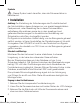
Symbole – Dieses Symbol weist daraufhin, dass die Dokumentation zu beachten ist. • Installation Achtung: Zur Einhaltung der Anforderungen der Produktsicherheit darf die Installation dieser Anzeigen nur von speziell ausgebildetem Fachpersonal, unter Beachtung der in dieser Dokumentation enthaltenen Informationen sowie der in dem jeweiligen Land geltenden Bestimmungen für die elektrische Verdrahtung und Sicherheitsvorschriften, durchgeführt werden.
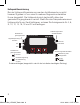
Die Anschlüsse für das Gerät befinden sich auf der Unterseite der Elektronik, die Polarität der Anschlüsse ist markiert. Anschlüsse Isolieren Sie die Anschlussleitung an beiden Enden auf 7 mm ab. Versehen Sie mehradrige Leiter mit einer geeigneten Adernendhülse (nicht löten). Verwenden Sie eine für Temperaturen von über 70 °C zugelassene Anschlussleitung (12-28 AWG), und schließen Sie diese mit einem Drehmoment von 0,5 Nm (4,5 lb-In) an.
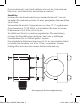
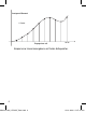
Anzeigewert/Messwert 11 Punkte Eingangsstrom mA 20 mA Beispiel einer Linearisierungskurve mit festen Haltepunkten. QS61001054_LPD450F_Buch.indb 6 25.01.
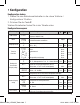
• Konfiguration Konfiguration ändern 1. Stellen Sie den Betriebswahlschalter in die obere ‘Kalibrier-/ Konfigurations’-Position 2. Drücken Sie die Taste P. Weitere Einzelheiten finden Sie in der Tabelle unten. Konfigurationssequenz Einstellung Anzeige Beschreibung P Å ì S/W Version v1.01 Softwareversion (Hinweis: Diese Tabelle bezieht sich nur auf die Versionen 1.00 bis 1.
Haltepunktlinearisierung Bei der Haltepunktlinearisierung werden die Messwerte von nicht linearen Signalen in Form einer in mehrere Segmente unterteilten Kurve dargestellt. Die Haltepunkte sind gleichmäßig über den gesamten Eingangsbereich verteilt. Wenn Sie also beispielsweise neun Haltepunkte für ein Gerät definieren, müssen Sie Anzeigewerte für 4, 6, 8, 10, 12, 14, 16, 18 und 20 mA festlegen.
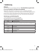
• Kalibrierung Allgemein Das LPD450F ist werksseitig kalibriert. Eine Neukalibrierung des Geräts ist vor der Installation in der Regel nicht notwendig. Führen Sie den Kalibriervorgang erst durch, nachdem das Gerät 15 Minuten in Betrieb war (und damit eine konstante Betriebstemperatur erreicht hat). Warten Sie während der Kalibrierung ein paar Sekunden, bis sich die Anzeige stabilisiert hat, bevor Sie den Wert übernehmen.
en LPD450F • Operation General The LPD450F is a field mount, 4+1/2 Digit, LCD Indicator for 4-20 mA signals. Loop powered operation The LPD450F draws its’ power from the 4-20 mA signal current, resulting in a voltage drop across the unit. The voltage drop (2.5 V @ 20 mA) is equivalent to an increase in loop load of 125 Ω. Cleaning The case can be wiped with a damp cloth. De-energise the unit before cleaning. Using the peak and valley hold feature To see the highest displayed value, hold down the ì key.
• Installation Caution: In order to meet product safety requirements, these units must only be installed, by qualified staff, in accordance with the information given in this manual, and all relevant national electrical wiring and safety rules must be followed. Industrial signals are frequently floating with respect to local earth, so take care while connecting the signal wires. The LPD450F is not intended to be connected to signals floating above 300 Vrms with respect to local earth.
Connections Strip wires to 7 mm from the ends. Use a suitable ferrule for multistranded wires (do not solder). Use 12-28 AWG Cu Wire rated for temperatures above 70 °C Only, tighten to 4.5 lb-In. For effective protection from electromagnetic noise, all signal cables must be shielded, or located on conductive trays or in conduits. The gland supplied suits a single sheath cable with diameter in the range 8 to 10 mm. Other cable sizes will require a different gland.
Display Value/Measurement 11 point Input Current mA 20 mA Curve suitable for fixed input interval breakpoint linearisation. QS61001054_LPD450F_Buch.indb 13 13 25.01.
• Setup Changing the set-up 1. Move run mode switch to the upper ‘calibrate/set-up’ position. 2. Press the P key. See table below for details. Setup Sequence Setting Display Description Å ì P S/W Version v1.01 S/W Version (Note: this table applies to versions 1.00 to 1.09 only) Mode SetP CALb Select for setup mode Select for calibrate mode Damping factor dF= 2 Transfer function FnC= LInr Srt 1oo1.5 1oo2.5 CurU Breakpoint linearistion display setup Introduces the number of breakpoints e.g.
Breakpoint linearisation Breakpoint linearisation gives a display of the measurement from nonlinear signals by breaking the curve up into a number of segments. The breakpoints are spread evenly throughout the input range. So, for example, if you set up a unit for nine breakpoints you will have to set display values for 4, 6, 8, 10, 12, 14, 16, 18 and 20 mA. Mann Series LPD450F P Switch positions (shown in correct position for installation). QS61001054_LPD450F_Buch.indb 15 15 25.01.
• Calibration General The LPD450F is factory calibrated. You should not have to recalibrate the unit before installation. Allow the instrument 15 minutes of powered operation (to reach a stable temperature) before calibration. During calibration allow a few seconds for signals to stabilise before accepting the value. Equipment requirements • A suitable 4-20 mA current source Input calibration procedure When the display shows Action/Description Connect the current source to the inputs and set to 4.00 mA.
QS61001054_LPD450F_Buch.indb 17 17 25.01.
QS61001054_LPD450F_Buch.indb 18 25.01.
QS61001054_LPD450F_Buch.indb 19 19 25.01.
Weidmüller Interface GmbH & Co. KG Postfach 3030 32720 Detmold Klingenbergstraße 16 32758 Detmold Tel. +49 5231 14-0 Fax +49 5231 14-20 83 info@weidmueller.com www.weidmueller.com QS61001054_LPD450F_Buch.indb 20 61001054/00/01.08 25.01.